Last Updated on 31/08/2026 by Bonnen Battery
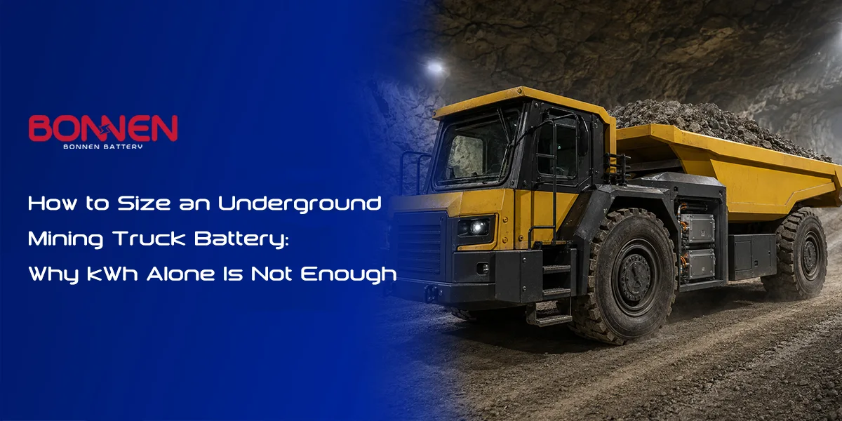
How to Size an Underground Mining Truck Battery: Why kWh Alone Is Not Enough
An underground mining truck battery should be sized from the complete haul cycle, not from payload or kWh alone. The correct battery is the smallest system that can complete the worst planned shift at its end-of-life condition, deliver continuous climbing power without derating, accept regenerative and charging power, stay within safe temperature limits, and fit the vehicle’s installation and maintenance space. A 624 kWh mining truck proves that large underground vehicles can be electrified, but it does not provide a battery specification that another mine can simply copy.
Battery sizing is therefore a system engineering task. It connects the truck, route, payload, motor, charger, cooling system, mine power supply, safety plan, and maintenance process.
1. What the LKAB 624 kWh Mining Truck Actually Proves

Scania has confirmed that LKAB is testing two custom semi-trailer electric trucks at its Malmberget underground mine in Sweden. Each truck has a payload of just over 70 tonnes and 624 kWh of installed battery energy.
The trucks are intended to move ore from underground chutes to crushers about 1,250 meters below the surface. They will initially operate for 16 hours across two shifts, with a future goal of continuous operation. The mine temperature is reported to remain around 12°C to 15°C, which is favorable for battery performance.
These are important facts, but they do not describe the complete battery specification. The public LKAB information does not confirm the pack voltage, usable SOC window, cell chemistry, number of battery boxes, continuous battery current, or charging power for these specific trucks.
Scania separately lists a 624 kWh battery configuration weighing about 3,540 kg in its current electric truck range. Scania’s regional electric truck platform has also been offered with charging power up to 375 kW. These figures help explain what a modern heavy truck platform can support, but they should not automatically be treated as confirmed LKAB mining truck specifications.
The trustworthy conclusion is simple: LKAB uses a custom 624 kWh system because its payload, route, shift plan, vehicle design, and charging strategy support that choice. Another 70-tonne truck may need much more or much less energy.
For a practical example of a scalable high-voltage platform, see our underground mining machine lithium battery system ⇱ for loaders, drilling trucks, haul trucks, and other battery-electric mining equipment.
Sources: Scania’s LKAB underground mining project ⇱, Scania battery configurations and weights ⇱, and Scania’s 624 kWh regional truck platform ⇱.
2. Start With the Haul Cycle, Not the Battery Catalogue

A haul cycle is one complete operating loop from loading to unloading and back again. For an underground truck, it normally includes loading, loaded travel, climbing or descending, unloading, empty return travel, waiting, and any charging opportunity.
Battery energy is consumed differently during each stage. A loaded uphill section may demand high continuous power. A downhill section may return energy through regenerative braking. Waiting at a chute uses little traction energy but may still require hydraulic pumps, cooling, lights, controls, and cab systems.
This is why a simple “hours of operation multiplied by average motor power” calculation is usually misleading. A 400 kW motor does not consume 400 kWh every hour. Motor rating describes capability, while real energy use depends on torque, speed, grade, payload, efficiency, and time.
A useful route model should include the following inputs:
| Haul-cycle input | Why it changes battery size |
| Empty vehicle mass | Affects rolling resistance and energy on every trip |
| Maximum payload | Changes climbing force, braking energy, and axle loads |
| One-way distance | Determines traction energy per cycle |
| Average and maximum grade | Strongly affects uphill power and downhill regeneration |
| Loaded travel direction | Loaded-uphill and loaded-downhill routes have very different energy profiles |
| Average and maximum speed | Changes power demand, cycle time, and cooling load |
| Acceleration requirement | Defines short peak power |
| Cycles per hour | Converts energy per cycle into shift energy |
| Shift length | Defines operating time between charging events |
| Road condition | Changes rolling resistance |
| Auxiliary power | Covers hydraulics, cooling, steering, lights, controls, and HVAC |
| Charging opportunities | Reduces the energy that must remain onboard |
| Minimum reserve SOC | Protects productivity when conditions differ from the plan |
–
A practical vehicle model calculates the force needed to overcome acceleration, road grade, and rolling resistance. At the low speeds common in underground haulage, aerodynamic drag may be much less important than it is for a highway truck.
A 2025 study using real mining work cycles describes traction force as the sum of inertia, climbing force, and rolling resistance. The study also shows why speed, road inclination, and carried load must be modeled as time-based data rather than one average number. See the IEEE Access study based on mining truck work cycles ⇱.
The best starting data is a time-based route log. GPS or mine-position data, speed, elevation, payload, motor torque, and hydraulic loads can reveal what the truck actually does. When measured data is not yet available, a route map and clearly stated assumptions can support a first estimate.
The same duty-cycle approach also applies to other off-highway battery pack designs ⇱, where working load, environment, peak current, cooling, and charging strategy must be considered together.
3. Energy and Power Are Two Different Sizing Problems

Energy is the amount of work the battery can supply over time. It is measured in kWh. Power is how quickly the battery can deliver or receive energy. It is measured in kW.
The distinction is critical:
| Requirement | What it controls |
| Installed energy in kWh | Potential operating time and range |
| Usable energy in kWh | Energy available inside the allowed SOC window |
| Continuous discharge power in kW | Ability to climb long grades without derating |
| Peak discharge power in kW | Starting, acceleration, breakout, and short steep grades |
| Peak duration | Thermal and electrical stress during a power event |
| Continuous charge power in kW | Normal charging speed |
| Peak regenerative power in kW | Ability to accept energy during downhill braking |
–
A battery can contain enough energy for an eight-hour shift but still be unable to supply the current needed for a long loaded climb. The opposite is also possible: a high-power battery may easily start the truck but contain too little energy to finish the shift.
Electrical power can be estimated with a simple formula:
* Power in kW = Voltage in V × Current in A ÷ 1,000
To calculate the required current:
* Current in A = Power in kW × 1,000 ÷ Voltage in V
For a simple first comparison, a 400 kW demand would require approximately 1,000 A at 400 V, 615 A at 650 V, or 500 A at 800 V. Actual battery current will change with the operating voltage and system efficiency.
| Nominal system voltage | Approximate current at 400 kW |
| 400 V | 1,000 A |
| 650 V | 615 A |
| 800 V | 500 A |
–
Lower current can reduce conductor size, connector heating, busbar losses, and contactor stress. However, higher voltage also increases requirements for insulation, creepage distance, clearance, testing, service procedures, and component selection.
Peak duration must always be stated. “500 kW peak” is incomplete because a five-second acceleration event is very different from a five-minute steep climb. The battery supplier needs a power-versus-time profile or, at minimum, continuous power, peak power, and the maximum duration of each peak.
Regenerative braking also has a power limit. A truck descending with a heavy load may produce more braking power than the battery can accept. The remaining energy must be controlled by the motor, resistor grid, mechanical brakes, or another system. The Global Mining Guidelines Group notes that regenerative braking needs enough battery SOC reserve and that battery and traction motor limits affect braking performance. See the GMG Recommended Practices for Underground Mining BEVs ⇱.
4. A Three-Step Method for First-Pass Battery Sizing
A first-pass estimate only needs three steps. First, calculate net energy per haul cycle. Second, multiply it by the number of cycles between charging events. Third, convert required usable energy into installed battery energy by including the SOC window, aging target, and operating reserve.
Step 1: Estimate net energy per haul cycle
Net cycle energy includes traction energy, auxiliary energy, electrical losses, and the energy recovered through regenerative braking.
Net energy per haul cycle = traction energy + auxiliary energy + system losses − recovered regenerative energy
For example, if one haul cycle requires 30 kWh of traction energy, 3 kWh of auxiliary energy, and 2 kWh of system losses, while regenerative braking returns 7 kWh, the net energy use is:
* 30 kWh + 3 kWh + 2 kWh − 7 kWh = 28 kWh per cycle
Regeneration should not be treated as free energy. Recovery is limited by motor efficiency, inverter limits, battery charge power, battery temperature, SOC, traction conditions, and the need to maintain safe braking.
It is safer to use a conservative regeneration estimate until real vehicle data is available.
Step 2: Calculate energy needed between charging events
If the truck uses 28 kWh per complete cycle and performs 12 cycles before charging, the expected energy demand is:
* 28 kWh per cycle × 12 cycles = 336 kWh
This number should include all meaningful auxiliaries. Mining vehicles can use significant energy for steering, hydraulic pumps, battery cooling, drivetrain cooling, air compressors, lighting, communication equipment, and cabin conditioning.
Step 3: Convert usable energy into installed energy
Installed capacity must be larger than the expected operating energy because the battery should not depend on its full nameplate capacity every shift.
A useful first-pass equation is:
* Installed battery energy = operating energy × reserve factor ÷ usable SOC factor ÷ end-of-life capacity factor
The percentage values must be entered as decimals. For example:
- 15% operating reserve = a reserve factor of 1.15
- 80% usable SOC window = a usable SOC factor of 0.80
- 80% remaining capacity at end of life = an end-of-life factor of 0.80
Consider a hypothetical truck that needs 350 kWh between charging events.
The project allows a 15% operating reserve, uses 80% of the battery’s SOC range, and requires the battery to complete the same work when its remaining capacity has fallen to 80% at the end of its planned life.
The calculation is:
* 350 kWh × 1.15 ÷ 0.80 ÷ 0.80 = approximately 629 kWh
The truck would therefore need about 629 kWh of installed battery capacity under these assumptions.
This does not mean every project needs both margins in exactly this form. Reserve, SOC window, and end-of-life capacity ⇱ must be agreed by the vehicle OEM, mine operator, and battery supplier. The example simply shows why 350 kWh of planned shift energy can lead to a battery close to 630 kWh.
Now assume that opportunity charging provides 120 kWh of usable energy during the shift.
The required onboard operating energy falls from 350 kWh to:
* 350 kWh − 120 kWh = 230 kWh
Using the same reserve, SOC window, and end-of-life assumptions:
* 230 kWh × 1.15 ÷ 0.80 ÷ 0.80 = approximately 413 kWh
In this example, opportunity charging reduces the estimated installed battery capacity from about 629 kWh to about 413 kWh.
Need a First Battery Size Estimate?
Send us your vehicle mass, payload, route distance, road grade, motor power, shift time, charging window, and available battery space. If some information is not final, that is fine. We can begin with your current data, mark the assumptions clearly, and identify what must be confirmed before detailed design.
5. Charging Strategy Can Change the Battery More Than Chemistry

A charging strategy defines when, where, and how the truck receives energy. It should be designed at the same time as the battery.
| Charging strategy | Main advantage | Main limitation |
| End-of-shift charging | Simple operating plan | Usually requires more onboard energy |
| Opportunity charging | Can reduce battery size | Depends on reliable natural downtime |
| Battery swapping | Short vehicle downtime | Requires handling equipment, spare batteries, and space |
| Trolley or dynamic supply | Can support long climbs and reduce battery demand | Adds fixed vehicle and mine infrastructure |
| Mixed strategy | Can balance productivity and battery size | Needs more control and planning |
–
Opportunity charging works best when it happens during an existing pause, such as loading, unloading, shift change, or operator break. A charging event that creates new downtime may reduce the productivity benefit of a smaller battery.
Charging time can be estimated with this formula:
* Charging time in hours = energy added in kWh ÷ average charging power in kW
For example, if the truck needs to receive 450 kWh and the average battery-side charging power is 300 kW:
* 450 kWh ÷ 300 kW = 1.5 hours
The estimated charging time is therefore 1.5 hours, or 90 minutes.
Average charging power should be used instead of charger nameplate power because battery temperature, SOC, charging limits, cable temperature, and power tapering can reduce the actual charging rate.
Mine power supply also matters. Several trucks connecting at once can create a large peak load. The project may require staged charging, load management, a local energy storage system, transformer upgrades, or a different charging schedule.
The charger must communicate with the BMS and vehicle control system. Charging should stop or reduce power when there is an insulation fault, coolant problem, excessive cell temperature, abnormal cell voltage, connector issue, or communication fault.
GMG recommends starting charging infrastructure design with the mine layout and vehicle operating map. Its guidance also notes that charging and swapping affect vehicle availability and utilization, which means charger planning is part of production planning rather than a separate electrical purchase.
6. Why High-Power Underground Trucks Usually Need Liquid Cooling
Battery heat is created during discharge, regenerative braking, and charging. Electrical losses rise roughly with the square of current, so a large increase in current can produce a much larger increase in resistive heating.
A mining truck can experience two difficult thermal events close together: a long loaded climb followed by high-power charging. A cooling system sized only for average operation may be unable to remove this combined heat load.
Thermal management has three jobs. It keeps cells within their safe operating range, limits temperature differences across the pack, and protects other high-current parts such as busbars, connectors, contactors, fuses, and cables.
Liquid cooling ⇱ is often preferred for high-power mining batteries because it can move heat more effectively from sealed, densely packed battery systems. It can also support battery heating in cold conditions by using the same coolant circuit with suitable controls.
Air cooling may still work for lower-power vehicles, smaller batteries, clean environments, or intermittent duty cycles. However, pulling dusty mine air through a battery enclosure can create contamination and maintenance problems. A sealed liquid-cooled pack separates battery airflow from the mine environment.
| Thermal question | Required design information |
| Maximum cell temperature | Worst continuous discharge and charge power |
| Cell-to-cell temperature difference | Cold-plate, coolant, and module layout |
| Coolant flow | Expected heat generation and pressure drop |
| Radiator or chiller size | Mine ambient temperature and heat rejection conditions |
| Low-temperature operation | Heating power and preheating time |
| Fault response | Pump, fan, sensor, valve, and coolant-leak behavior |
–
Battery temperature should not be reduced to one fixed “ideal” number. The approved temperature range depends on the selected cell, power demand, charging rate, life target, and BMS control strategy.
NREL research has long identified both temperature and temperature uniformity as important factors in battery performance. See NREL’s paper on designing battery thermal management systems ⇱.
In our heavy-equipment battery work, thermal design often changes after the continuous power and charging schedule become clear. This is why “liquid cooled” should not be treated as a complete specification. Coolant type, flow, inlet temperature, heat rejection capacity, control logic, and fault handling still need to be defined.
7. Should the Truck Use 400 V, 650 V, or 800 V?
System voltage is a vehicle-level decision. It must match the motor inverter, charger, DC/DC converter, accessories, connectors, contactors, insulation system, and service process.
A higher voltage reduces current for the same power. This can help control cable size and heat in a high-power vehicle. However, it does not automatically make the battery smaller or safer.
The real specification must include the complete battery voltage window, not only nominal voltage. The inverter and charger must operate from the pack’s maximum charge voltage down to its minimum allowed discharge voltage.
| Design factor | Lower-voltage system | Higher-voltage system |
| Current at equal power | Higher | Lower |
| Cable and busbar demand | Often larger | Can be smaller |
| Resistive heating | Usually higher at equal conductor size | Usually lower |
| Component availability | May be easier for moderate power | Must be checked for the target voltage |
| Insulation requirements | Lower | Higher |
| Service and test controls | Strict | More demanding |
| Fast-charging potential | More current-limited | Can support higher power with less current |
–
Voltage should therefore be selected from the complete powertrain architecture. Choosing 800 V simply because it sounds modern can create cost and integration problems. Choosing 400 V for a very high-power truck may create extreme current and heavy conductors.
The best system voltage is the lowest practical voltage that still meets power, current, charging, component, and vehicle integration limits with an acceptable margin.
8. Underground High-Voltage Safety Must Be Designed as a System
An underground battery is not safe because it uses one particular chemistry. Safety comes from layers of prevention, detection, isolation, containment, and emergency response.
The high-voltage system should normally include:
| Safety function | Purpose |
| Insulation monitoring device | Detects loss of insulation between the HV system and chassis |
| High-voltage interlock loop | Detects an opened connector, cover, or service point |
| Precharge circuit | Limits inrush current before main contactors close |
| Main contactors | Connect and isolate the traction battery |
| Properly coordinated fuses | Interrupt dangerous overcurrent and short-circuit events |
| Manual service disconnect | Provides a controlled maintenance isolation point |
| Emergency stop interface | Allows the vehicle to enter a defined safe state |
| Cell and component temperature monitoring | Detects abnormal heating early |
| Coolant and pump monitoring | Prevents operation without required cooling |
| Pressure management and venting | Directs released gases away from people and critical equipment |
| Mechanical guards | Protect against rock strike, bottom impact, collision, and debris |
| BMS fault derating | Reduces power before a condition becomes critical |
| Event logging | Supports maintenance, diagnosis, and incident review |
–
Many of these protection functions are coordinated by the Battery Management System (BMS) ⇱, which manages high-voltage switching, charging limits, insulation monitoring, HV interlock status, temperature protection, and fault response.
An insulation monitoring device, or IMD, continuously checks insulation resistance between an unearthed HV system and earth or chassis. IEC 61557-8 specifies requirements for IMDs used on unearthed DC systems up to 1,500 V. See the IEC 61557-8 standard overview ⇱.
GMG also recommends insulation and ground-fault monitoring, HV interlocks, emergency stop functions, overcurrent protection, automatic shutdown, condition monitoring, and vehicle-specific fire planning.
Fire risk requires special attention underground because heat, smoke, toxic gases, and evacuation constraints can affect areas far from the vehicle. The OEM should provide credible failure scenarios, detection logic, isolation behavior, vent direction, emergency instructions, and information about the battery chemistry.
A conventional sealed or explosion-proof enclosure should not be assumed to contain every lithium-ion thermal runaway event. A NIOSH experiment found that a tested explosion-proof enclosure did not adequately contain the jet flames and pressure produced by thermal runaway under the specific test conditions. The researchers recommended considering pressure, hot gases, free space, cascade prevention, venting, and flame-arresting methods. See the NIOSH underground battery enclosure study ⇱.
The exact fire strategy must reflect the mine type. A metal mine, a gassy coal mine, and a surface mine can have different legal and technical requirements. Local mine regulations and the site emergency plan always take priority.
9. One Large Battery or Several Distributed Packs?

A large battery does not have to be one large box. Several high-voltage battery packs can be connected to a common vehicle DC bus when the electrical architecture and control system are designed for it.
Distributed packs may fit the chassis better, improve axle-load balance, and allow smaller service units. They can also shorten some cable or coolant routes. However, they add connectors, contactors, coolant branches, communication nodes, mounting points, and fault-management requirements.
| One large pack | Multiple distributed packs |
| Fewer external HV connections | Easier packaging around the chassis |
| Simpler coolant interface | Can improve mass distribution |
| Large lifting and service load | Smaller individual service units |
| May be difficult to fit or remove | More connectors and communication links |
| One enclosure fault may affect the whole system | Fault isolation can be more flexible |
| Requires large maintenance clearance | Requires access to several locations |
–
Parallel high-voltage packs also need careful control. Packs should not be connected together with a large voltage or SOC difference. The design may require separate contactors, fuses, current measurement, pack controllers, precharge logic, and controlled connection sequences.
Mechanical integration deserves the same attention as electrical design. Good battery enclosure design ⇱ must consider pack dimensions, mass, center of gravity, mounting loads, removal direction, lifting points, fork pockets, service access, connector space, cooling couplings, drainage, vent direction, and rock-impact protection.
IP67 may be a useful enclosure target, but an IP rating does not prove resistance to vibration, stone impact, corrosion, pressure washing, coolant leaks, or long-term seal aging. Those requirements need separate tests. ISO 20653 explains the scope of vehicle enclosure IP codes and the related dust and water tests. See ISO 20653:2023 ⇱.
A pack that fits in CAD but cannot be safely removed underground is not fully integrated.
10. How to Validate the Battery Before Production

A mining battery should be validated against its real application rather than a generic test list alone.
The process begins with an agreed design-input document. It should identify the vehicle, mine environment, electrical interfaces, route, duty cycle, safety goals, service plan, legal requirements, and acceptance criteria.
The next stage is model-based validation. Engineers should check energy use, continuous and peak current, regenerative power, charge time, cell temperature, coolant flow, voltage range, fault current, insulation coordination, axle loads, and structural loads.
Physical testing then confirms the model. Depending on the project, this may include capacity and power tests, repeated duty-cycle testing, high- and low-temperature operation, fast charging, thermal balance, coolant pressure and leakage tests, insulation resistance, dielectric withstand, IP testing, vibration, mechanical shock, connector durability, CAN communication, BMS fault injection, emergency shutdown, and charger compatibility.
ISO 12405-4 provides test procedures for the performance, reliability, and electrical functionality of EV battery packs and systems. IEC 60068-2-64 covers broadband random vibration, while IEC 60068-2-27 covers mechanical shock. These standards can support a test plan, but the vibration and shock profile should still represent the actual mining vehicle.
Sources: ISO 12405-4 battery performance testing ⇱, IEC 60068-2-64 random vibration testing ⇱, and IEC 60068-2-27 shock testing ⇱.
The final stage is vehicle validation. A prototype should be tested on a representative route with the expected payload. Engineers should record battery current, voltage, SOC, cell temperatures, coolant temperatures, motor power, regenerative power, charger data, route time, faults, and auxiliary energy.
A short successful demonstration is not enough. The test should include the worst credible continuous climb, repeated cycles, low and high SOC, charging after heavy operation, and planned fault responses.
After commissioning, logged data should be compared with the original model. The model can then be updated to improve SOC prediction, thermal control, charging schedules, maintenance intervals, and future pack sizing.
11. What Information Should an OEM Send for Battery Design?
The fastest way to size a mining truck battery is to collect the right vehicle and operating data before fixing the battery capacity.
| Required information | Minimum useful detail |
| Vehicle configuration | Truck type, axle layout, empty mass, and gross vehicle mass |
| Payload | Normal and maximum payload |
| Route | Distance, elevation profile, average grade, and maximum grade |
| Loaded direction | Loaded uphill, loaded downhill, or mixed |
| Operating plan | Shift length, cycles per hour, and expected availability |
| Motor and inverter | Nominal voltage, continuous power, peak power, and peak duration |
| Regenerative braking | Maximum motor and inverter regeneration power |
| Auxiliary loads | Hydraulic, cooling, steering, HVAC, lighting, and controls |
| Charging plan | Available time, charger power, connector, and mine power limit |
| Battery space | CAD envelope, mounting points, removal direction, and service space |
| Environment | Temperature, dust, water exposure, vibration, impact, and altitude |
| Cooling interface | Vehicle coolant loop or independent battery cooling |
| Communication | CAN protocol, messages, control ownership, and diagnostics |
| Safety requirements | IMD, HVIL, emergency stop, fire strategy, and mine regulations |
| Life target | Operating days, cycles, usable SOC window, and end-of-life capacity |
| Certification | Country, mine type, vehicle category, and required standards |
–
Not every project has complete data at the beginning. A concept-stage OEM may not yet know the final inverter, charger, route, or battery compartment.
That is not a reason to stop. The battery design can begin with known values and controlled assumptions. Each assumption should be marked as provisional, assigned an owner, and replaced with measured or approved data before design freeze.
From our experience with custom lithium battery pack design ⇱, the first customer request often includes voltage and kWh but leaves out peak duration, loaded travel direction, charging time, and maintenance access. These missing details can change the cell choice, pack count, cooling system, current rating, enclosure, and cost.
The final selection rule is straightforward: size energy from the worst operating period between charges, size power from the hardest continuous and peak events, size cooling from repeated power and charging heat, and size the enclosure from the real vehicle and service environment.
Planning an Underground Mining Vehicle Battery?
Share the information you already have, even if your design is still at the concept stage. We can review your vehicle voltage, power, payload, route, charging plan, temperature range, and installation space, then identify the missing inputs needed for a reliable battery proposal.
Your project does not need to be fully defined before the first discussion. CAD files, route data, motor specifications, or even a clear written concept can be enough to begin. NDA support is available for OEM projects.
12. FAQ
How do I size a battery for an underground mining truck?
Start with the complete haul cycle: vehicle mass, payload, route distance, grade, speed, auxiliary loads, cycles per shift, regenerative braking, and charging opportunities. Calculate the usable energy needed between charging events, then adjust it for the SOC window, operating reserve, and required end-of-life capacity. Power, cooling, safety, and installation limits must be checked separately.
How many kWh does an electric mining truck need?
There is no universal kWh value for an electric mining truck. Smaller underground trucks may use batteries below 200 kWh, while very heavy vehicles can exceed 600 kWh. The correct capacity depends more on route grade, payload direction, cycle frequency, charging access, and shift length than on vehicle tonnage alone.
Is a 624 kWh battery suitable for every 70-tonne mining truck?
No. A 624 kWh battery may suit one 70-tonne truck but be too large or too small for another. A truck carrying ore uphill for long distances usually needs more energy than one carrying ore downhill and recovering part of its braking energy. Charging windows and required operating hours can also change the result significantly.
What is the difference between installed and usable battery capacity?
Installed capacity is the total nameplate energy inside the battery, while usable capacity is the energy available within the approved SOC window. A 624 kWh battery operating through a 75% SOC window provides about 468 kWh before other operational or aging limits are considered. Usable energy, not installed energy alone, determines practical operation.
How do I calculate mining truck battery energy per shift?
Estimate net energy per haul cycle, including traction, auxiliaries, system losses, and conservative regenerative braking. Multiply this value by the planned number of cycles between charging events. Then add an operating reserve and adjust for the usable SOC window and required battery capacity at end of life.
Why is continuous battery power important for an underground haul truck?
Continuous power determines whether the truck can complete a long loaded climb without battery, inverter, motor, or cooling-system derating. A large kWh battery may still fail this requirement if its cells, busbars, connectors, contactors, or cooling system cannot support the required current for the full climbing time.
How long should peak battery power be available?
Peak duration should match the longest real high-power event, such as starting on a grade, accelerating with a full load, or crossing a short steep ramp. A peak rating without duration is incomplete. Five seconds, one minute, and five minutes create very different electrical and thermal requirements.
How does road grade affect electric mining truck battery size?
Road grade changes both power and energy demand. Loaded uphill travel increases traction force and may create long periods of high battery current. Loaded downhill travel can return energy through regenerative braking, but recovery is limited by SOC, temperature, traction, and battery charge power. The complete elevation profile should be modeled.
How much energy can an underground mining truck recover through regenerative braking?
The recoverable amount depends on vehicle mass, elevation loss, speed, motor and inverter limits, drivetrain efficiency, battery SOC, battery temperature, and maximum charge power. It should be calculated from the route and then reduced by realistic system limits. A conservative estimate is safer than assuming all downhill potential energy returns to the battery.
Can opportunity charging reduce mining truck battery capacity?
Yes. Opportunity charging during loading, unloading, shift changes, or planned breaks can reduce the energy that must be stored onboard. The benefit depends on usable energy delivered during the stop, not charger nameplate power. Charging time, power tapering, mine grid capacity, connector handling, and operational reliability must all be included.
How fast can a 600 kWh mining truck battery be charged?
Charging time depends on usable energy added and average battery-side power. Adding 450 kWh at an average of 300 kW takes about 1.5 hours before additional connection or operating time is considered. A charger rated at 375 kW may deliver a lower average because battery temperature, SOC, and the charge curve can limit power.
Does an underground mining truck battery need liquid cooling?
A high-power underground truck will often benefit from liquid cooling because it may combine long climbing loads, regenerative braking, fast charging, sealed enclosures, and dusty conditions. Liquid cooling is not automatically required for every vehicle, but the cooling method must be verified against continuous discharge, charging heat, temperature uniformity, and mine conditions.
Should an electric mining truck use LFP or NMC batteries?
LFP is often considered when cycle life, thermal stability, and robust daily use are priorities. NMC may be considered when battery mass and installation space are more restricted. Chemistry should not be chosen from one advantage alone; power, temperature, charging, enclosure safety, pack mass, route, life target, and local mine rules must be evaluated together.
Is 800 V better than 400 V for a mining truck?
Not always. An 800 V system can deliver the same power at roughly half the current of a 400 V system, which can reduce conductor and cooling demands. It also requires compatible high-voltage components, stronger insulation control, suitable chargers, and stricter service procedures. The complete powertrain should determine the voltage.
Why does an underground mining truck need insulation monitoring?
Most traction HV systems are designed to remain isolated from the vehicle chassis. An IMD detects a reduction in insulation resistance that could create shock, arc, or equipment-damage risk. It allows the vehicle control system to warn the operator, restrict operation, or shut down according to the defined fault level.
What safety features should a high-voltage mining battery include?
A typical system may include insulation monitoring, HV interlock, precharge, contactors, coordinated fuses, a manual service disconnect, emergency stop input, cell and component temperature sensing, coolant monitoring, pressure management, event logging, CAN-based fault control, mechanical protection, and a site-specific emergency response plan.
Is IP67 enough for an underground mining truck battery?
No. IP67 addresses defined dust and temporary water-immersion tests, but it does not prove that the pack can withstand long-term vibration, rock impact, pressure washing, corrosion, coolant leaks, seal aging, or thermal-runaway pressure. Each environmental and mechanical risk needs its own design requirement and test method.
Is one large battery pack better than several smaller packs?
Neither layout is always better. One large pack can reduce external connections, while distributed packs can improve packaging, mass balance, and service handling. Multiple packs add connectors, coolant branches, pack controllers, protection devices, and connection logic. The choice should follow vehicle space, axle loads, maintenance access, and fault-isolation needs.
What information do I need to request a custom mining truck battery?
Provide the vehicle mass, payload, route distance, grade profile, loaded travel direction, shift time, motor voltage, continuous and peak power, peak duration, regenerative power, charging time, charger rating, battery installation space, temperature range, cooling interface, communication protocol, IP target, and applicable mine regulations. Incomplete concept-stage data can still support an initial review.
How should an underground mining truck battery be tested?
Testing should reflect the real route and environment. A complete plan may include capacity, power, repeated duty cycles, charging, thermal balance, coolant leakage, insulation, dielectric withstand, BMS fault response, CAN communication, vibration, shock, ingress protection, connector durability, emergency shutdown, and loaded vehicle testing on a representative grade.
How much battery reserve should a mining truck have?
There is no fixed reserve for every mine. The reserve should cover route variation, waiting time, temperature, battery aging, unexpected auxiliary use, charging delays, and recovery to a safe location. It should be agreed as part of the mine operating plan rather than added as an unexplained percentage at the end.
Can I size a mining truck battery if the final vehicle design is not complete?
Yes. Begin with the best available payload, route, power, charging, and space estimates. Mark uncertain values as assumptions and run several scenarios. The battery concept can then be updated as the motor, inverter, CAD envelope, duty cycle, and mine infrastructure become final. Detailed design should not be frozen until critical inputs are approved.
Technical References and Further Reading
* Scania: LKAB Takes Electrification Underground: Confirms the LKAB truck payload, 624 kWh installed energy, operating depth, and mine conditions.
* GMG Recommended Practices for Underground Mining BEVs: Covers mine design, charging, batteries, safety, maintenance, and performance planning.
* IEEE Access: Off-Highway Mining Truck Electrification: Provides a work-cycle vehicle model using mass, acceleration, grade, and rolling resistance.
* NREL Battery Thermal Management Design: Explains the importance of battery temperature and temperature uniformity.
* NIOSH Study of Thermal Runaway in an Explosion-Proof Enclosure: Examines pressure, flames, gases, venting, and enclosure limitations in mining applications.
* IEC 61557-8 Insulation Monitoring Devices: Defines IMD requirements for unearthed AC and DC systems.
* ISO 12405-4 Battery Pack Performance Testing: Covers battery pack performance, reliability, and electrical functionality testing.
* ISO 20653:2023 Vehicle Enclosure IP Codes: Defines vehicle electrical enclosure protection against dust, water, and access.
Contact Bonnen Battery↓ now and let us help you power your adventures with the best lithium battery technologies.
© [Bonnen Battery] and [www.bonnenbatteries.com]. Unauthorized use and/or duplication of this material without express and written permission from this site’s author and/or owner is strictly prohibited. Excerpts and links may be used, provided that full and clear credit is given to [Bonnen Battery] and [www.bonnenbatteries.com] with appropriate and specific direction to the original content.
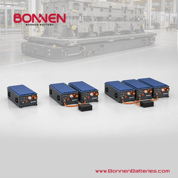
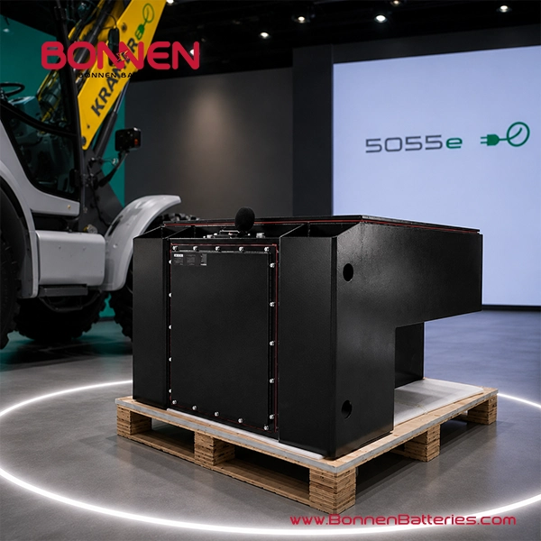
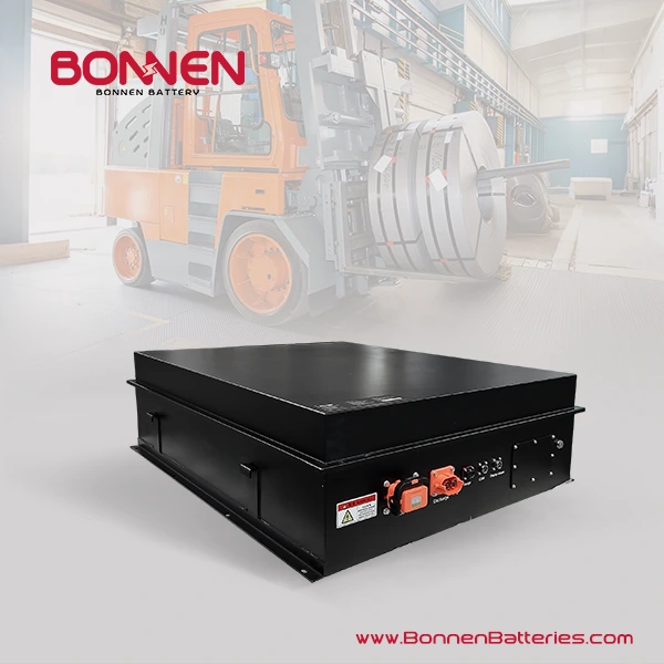
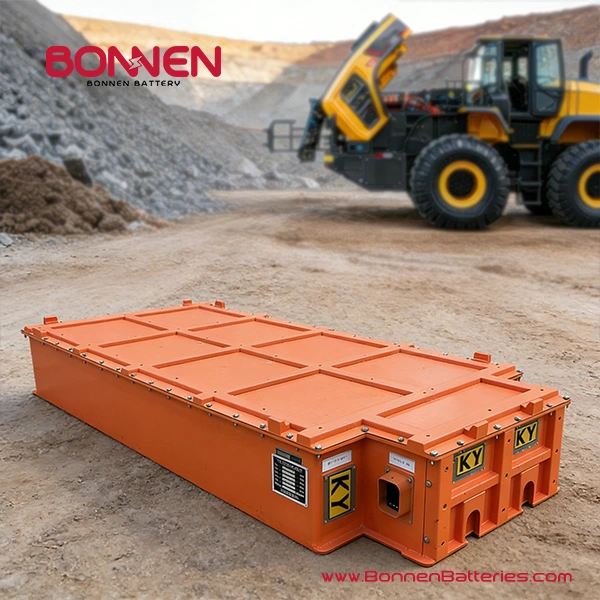
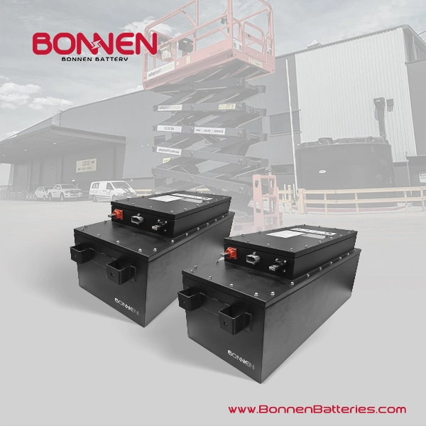
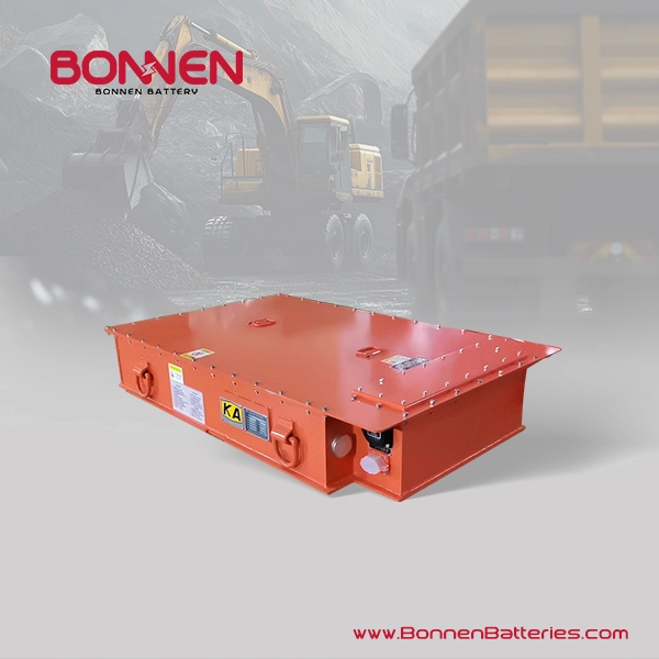
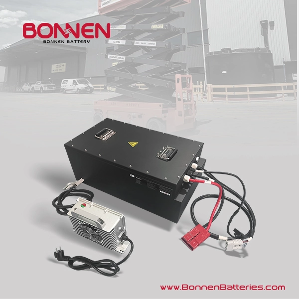
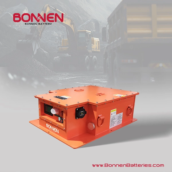
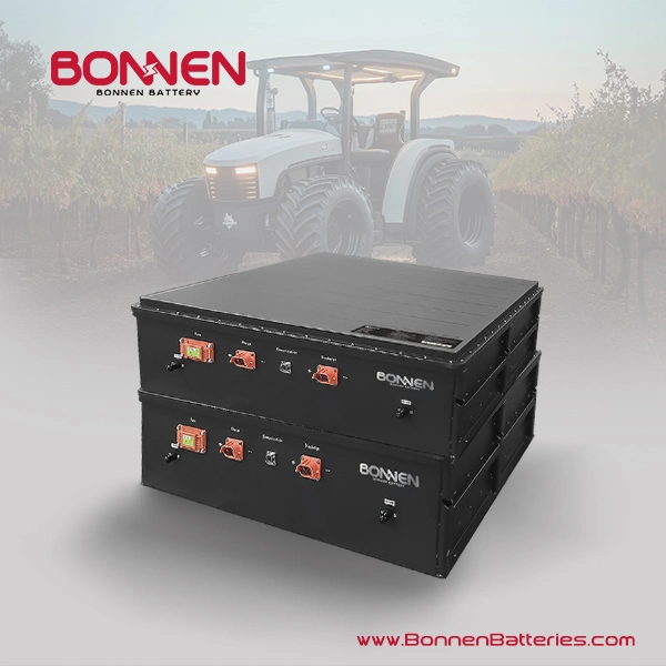
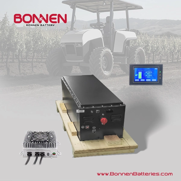
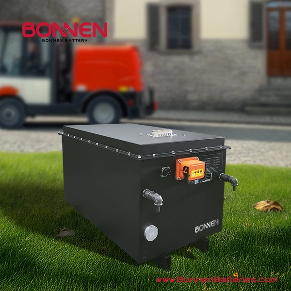
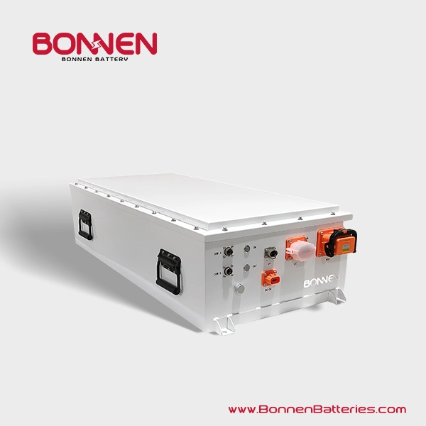
Heavy Equipment Lithium Batteries from Bonnen Battery
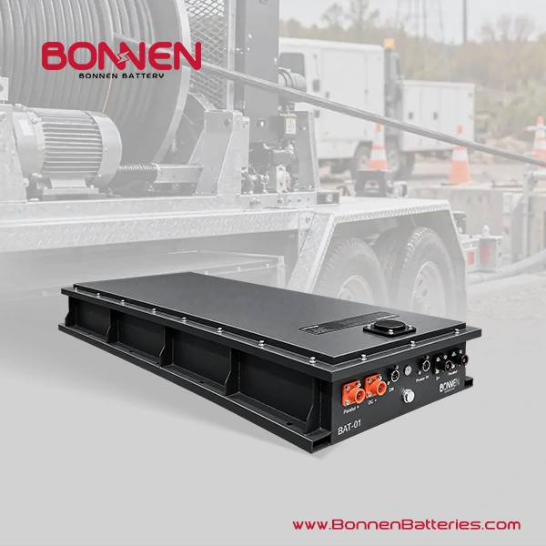

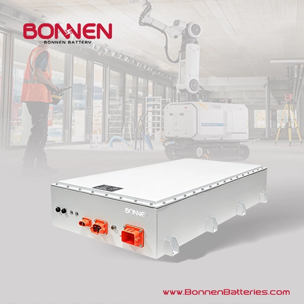
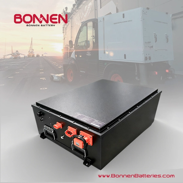
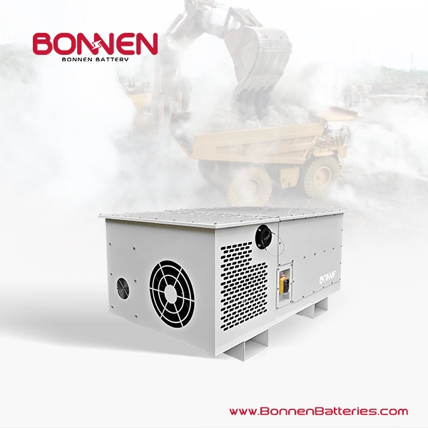
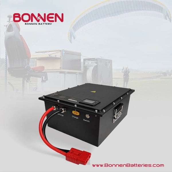
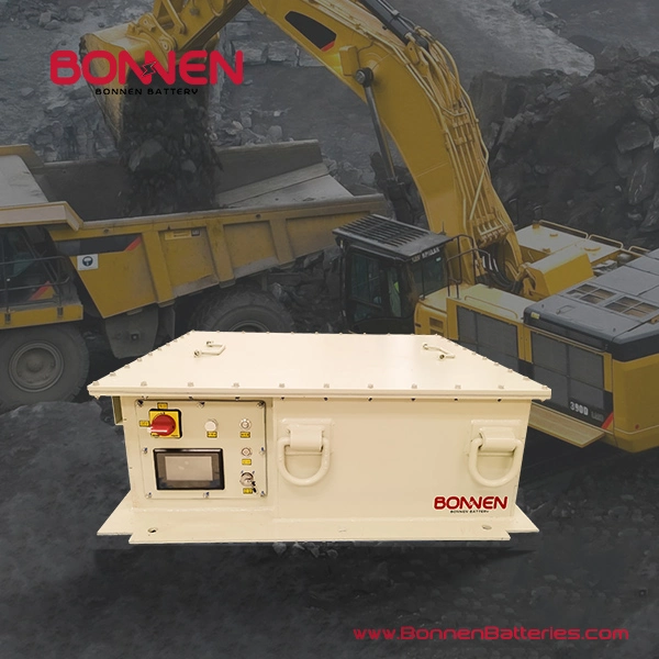
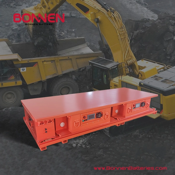
600V 614V 500Ah LiFePO4 Battery System: The Essential Heavy Equipment Lithium Battery for Construction, Agricultural, Mining, and Traction Applications