Last Updated on 14/10/2026 by Bonnen Battery
BMS CAN Bus Integration Guide for OEM Battery Packs
Integrating a lithium battery BMS with a motor controller, charger, inverter, or other equipment through CAN bus requires more than connecting two communication wires. Both devices must use compatible CAN settings, message formats, and control logic. A successful integration allows the battery and equipment to exchange important information, including state of charge (SOC), voltage, current, temperature, charging limits, and fault status. However, having a CAN port does not automatically mean two devices can communicate or work safely together.
For OEM engineers, the real challenge is not getting CAN messages onto the network. It is making sure the entire system responds correctly to those messages.
For example, a motor controller might receive battery voltage and SOC without any problems. But what happens when the BMS reduces the maximum discharge current because the battery is getting too hot? Will the controller reduce power, ignore the message, or shut down unexpectedly?
That is where proper system integration becomes important.
This guide explains how BMS CAN bus communication works, what information OEMs need before starting integration, how to connect and configure devices, and how to test the complete system. It also covers common communication problems, multiple-battery systems, and practical requirements for electric vehicles, marine propulsion, industrial equipment, robots, and energy storage systems.
1. What Is CAN Bus Communication in a Battery Management System?
CAN stands for Controller Area Network. It is a communication system that allows electronic devices to exchange information over a shared network.
Originally developed for automotive applications, CAN bus is now widely used in industrial machinery, electric vehicles, marine equipment, robots, and battery energy storage systems.
In a lithium battery system, the battery management system (BMS) monitors the cells and protects the battery against unsafe operating conditions.
Depending on its design, the BMS may measure cell voltage, pack current, temperature, SOC, and other operating conditions. It may also control contactors, manage charging and discharging limits, and report faults.
CAN bus allows the BMS to share selected information with external equipment.
For example, the BMS can tell a motor controller that the battery is at 25% SOC or report that the available discharge current has been reduced because of low temperature.
The controller can then use that information to manage the equipment.
What is the difference between CAN bus and a BMS CAN protocol?
This is one of the most important points to understand.
CAN bus provides the communication method. The BMS communication protocol defines what the messages mean and how devices should respond.
Think of CAN bus as a telephone connection. Having a working phone line does not help much if the two people speak different languages.
The same applies to a battery and motor controller.
Two devices might use identical CAN hardware and the same communication speed. However, they may still be incompatible because they use different CAN identifiers, data formats, or operating commands.
A CAN connection is only the beginning of integration.
For a more detailed explanation of the underlying technology, see the CAN Bus Explained guide from CSS Electronics ⇱.
2. How Does a BMS Communicate with Other OEM Equipment?
In an OEM battery system, the BMS rarely works alone.
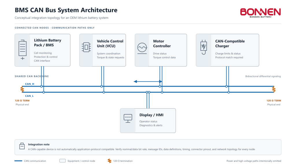
It may communicate with a vehicle control unit (VCU), motor controller, onboard charger, inverter, power conversion system (PCS), or monitoring display.
The exact communication architecture depends on the equipment and application.
A basic electric vehicle system might include a battery pack, BMS, VCU, motor controller, and charger.
The BMS monitors battery conditions and sends information to the VCU. The VCU then manages vehicle operation according to the battery’s available power and operating status.
In another system, the BMS may communicate directly with the motor controller without a separate VCU.
Neither architecture is automatically better. The correct choice depends on the system design and the responsibilities assigned to each device.
Typical communication between the BMS and other equipment
| Connected Equipment | Information Exchanged | Main Purpose |
|---|---|---|
| Motor Controller | SOC, voltage, discharge limits, faults | Manage motor operation and available power |
| VCU | Battery status, operating permissions, power limits, warnings | Coordinate vehicle operation |
| Battery Charger | Charging voltage limit, current limit, charging status | Coordinate charging |
| Inverter / PCS | SOC, voltage, charge and discharge limits, alarms | Manage energy conversion |
| Display / HMI | SOC, current, temperature, alarms | Show battery information |
| Gateway / Telematics | Battery data, diagnostic information | Remote monitoring and data collection |
Not every BMS sends all these values.
Some basic BMS models only provide battery status and fault information. More advanced systems can support dynamic current limits, operating commands, contactor status, and other functions.
That is why the BMS specification must be reviewed before selecting it for an OEM project.
Monitoring data and control commands are not the same
A useful distinction is whether a CAN message only reports information or is involved in controlling system behavior.
For example, reporting SOC to a display is mainly a monitoring function.
Sending a charge current limit to a charger is different. The charger must correctly interpret that information and adjust its output.
Similarly, a message requesting contactor operation should be handled through defined safety checks rather than treated as an unrestricted command.
For reliable integration, engineers must understand both the message content and the expected response.
3. BMS CAN Bus Wiring, Baud Rate, and Message Format
Before troubleshooting software or protocols, make sure the physical communication network is correct.
A surprising number of CAN integration problems come from basic wiring, termination, or configuration mistakes.
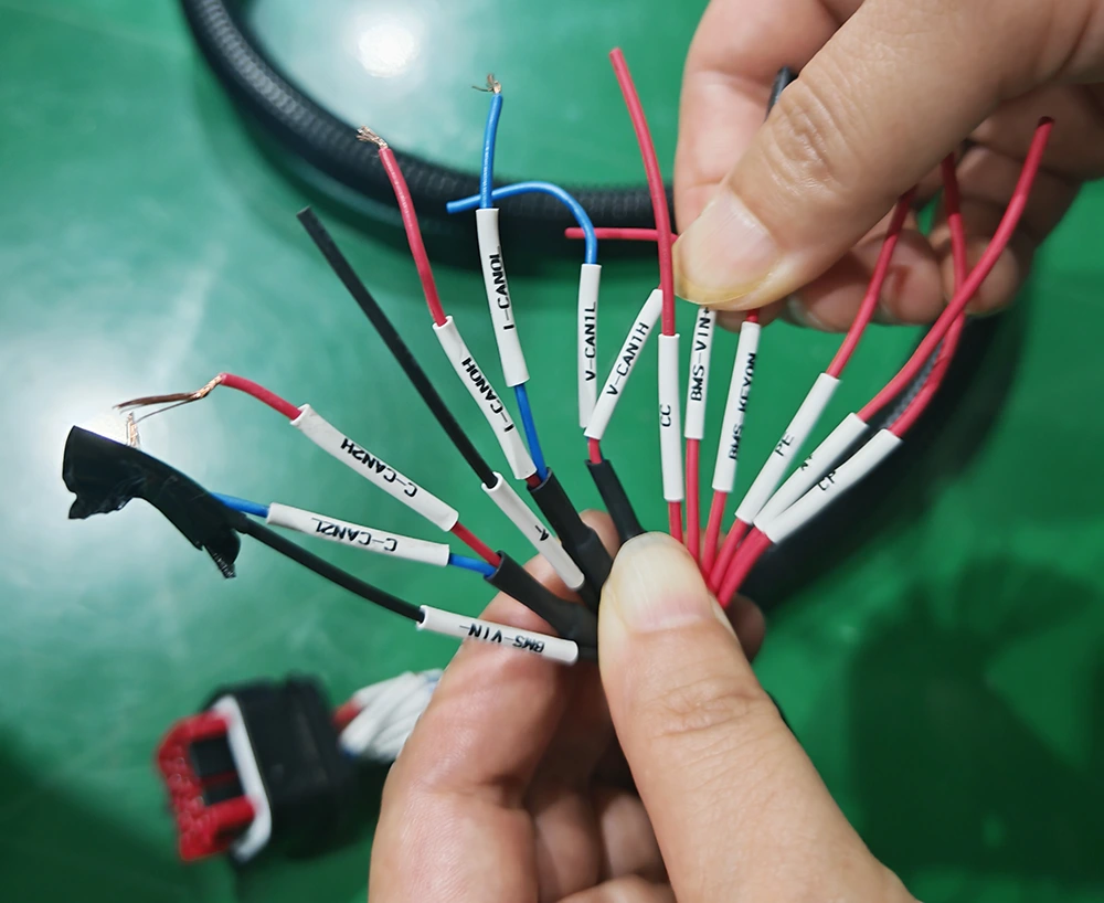
CAN-H and CAN-L wiring
A typical high-speed CAN network uses two signal wires:
CAN-H (CAN High) and CAN-L (CAN Low).
The network sends information using the voltage difference between these two lines. This differential signaling helps CAN communication resist electrical interference.
CAN wiring commonly uses twisted-pair cable. Depending on the application, shielding, grounding, electrical isolation, and additional protection may also be required.
One important warning: connector appearance does not guarantee pin compatibility.
Two devices may use the same RJ45 or circular connector but assign CAN-H, CAN-L, ground, and other signals to different pins.
Always follow the pinout provided by each manufacturer.
Why does CAN bus need termination resistors?
A typical high-speed CAN network uses a 120-ohm termination resistor at each physical end of the bus.
These resistors help reduce signal reflections that can cause communication errors.
With two 120-ohm resistors connected in parallel, the resistance measured between CAN-H and CAN-L is normally approximately 60 ohms when the network is powered down and measured under the correct conditions.
This is a useful diagnostic check, but the result depends on the actual network design and connected hardware.
| Measured Resistance | Possible Explanation |
|---|---|
| Approximately 60 Ω | Two 120 Ω terminations are likely present |
| Approximately 120 Ω | One termination may be missing |
| Approximately 40 Ω | There may be three 120 Ω terminations |
| Very high resistance | Open wiring or missing termination |
| Very low resistance | Possible short circuit or incorrect wiring |
These readings are diagnostic clues, not final proof that the CAN network is correctly installed.
For detailed testing guidance, see Kvaser’s CAN termination testing guide ⇱.
Resistance measurements should only be performed on a safely powered-down and appropriately isolated communication circuit. High-voltage battery enclosures should not be opened by unqualified personnel.
What CAN baud rate should a battery BMS use?
The baud rate defines the communication speed.
Common Classical CAN speeds used in battery and industrial applications include 125 kbps, 250 kbps, and 500 kbps.
For example, a custom industrial battery system might use 250 kbps, while a compatible third-party battery interface on certain Victron systems may use a 500 kbps BMS-Can profile.
There is no single baud rate suitable for every BMS.
The correct value must match the required communication network.
Changing the baud rate alone will not make incompatible protocols work together.
Understanding CAN identifiers and data frames
A CAN message includes an identifier and a data payload.
Classical CAN supports 11-bit and 29-bit identifiers, with up to eight data bytes in a standard data frame.
A CAN identifier helps receiving devices recognize messages and also participates in message priority.
However, CAN itself does not define what the payload means.
A manufacturer might assign one message to battery voltage and another to SOC. Another manufacturer may use completely different identifiers and data layouts for the same information.
For each message, engineers may need to define:
| Parameter | What It Means |
|---|---|
| CAN ID | Identifies the message |
| Frame Format | 11-bit standard or 29-bit extended |
| Data Length | Number of data bytes |
| Byte Order | How multi-byte values are arranged |
| Scale Factor | Converts raw data to engineering values |
| Offset | Additional conversion value |
| Message Period | How often the message is transmitted |
| Timeout | When missing communication is considered a fault |
CAN FD is another version of CAN that supports larger payloads and different data-phase speeds. However, a CAN FD interface should not be assumed to be interchangeable with a Classical CAN device without confirming compatibility and configuration.
4. Common BMS CAN Bus Protocols Explained
A CAN interface does not automatically define the application protocol.
Different industries have developed communication standards and conventions for specific equipment.
Understanding these differences is important when choosing a BMS for a custom lithium battery.
Comparison of common CAN communication protocols
| Protocol / Interface | Typical Applications | Key Integration Considerations |
|---|---|---|
| Proprietary CAN | Custom EVs, industrial equipment, robots | Requires the manufacturer’s message definitions |
| SAE J1939 | Commercial vehicles, tractors, heavy equipment | Uses defined communication structures, PGNs, and SPNs |
| CANopen | Industrial automation, motion control | Uses device profiles, object dictionaries, and network management |
| NMEA 2000 | Marine equipment and vessel monitoring | Requires compatible marine network messages and device behavior |
| Victron BMS-Can | Supported managed batteries and Victron GX systems | Requires the correct protocol, configuration, and compatible equipment |
| CAN FD | Modern embedded and industrial systems | Requires compatible CAN FD hardware and communication settings |
These terms do not all describe the same technical layer.
CAN and CAN FD describe communication technologies, while standards such as J1939 and CANopen define additional rules for exchanging and interpreting data.
SAE J1939 for vehicles and heavy equipment
SAE J1939 is commonly used in commercial vehicles, agricultural machinery, construction equipment, and other heavy-duty applications.
It uses 29-bit CAN identifiers and organizes information using Parameter Group Numbers (PGNs) and Suspect Parameter Numbers (SPNs).
PGNs identify message groups, while SPNs describe individual parameters.
For an OEM battery project, confirming support for J1939 is not enough. Engineers must also check which messages are implemented and whether the required battery information is available.
A BMS might support selected J1939 functions without supporting every message required by a particular vehicle controller.
See the J1939 technical guide from CSS Electronics ⇱ for more details.
CANopen for industrial automation
CANopen is used in many industrial automation applications.
It defines communication mechanisms and uses an object dictionary to organize device parameters.
However, devices using CANopen are not automatically interchangeable.
Their device profiles, communication objects, operating modes, and supported functions must match the application.
For an industrial battery, the engineering team should confirm whether the BMS uses a standard device profile or a manufacturer-specific implementation.
More information is available from CAN in Automation ⇱.
NMEA 2000 for marine battery systems
NMEA 2000 is a marine communication standard based on CAN technology.
It allows compatible equipment to exchange information such as navigation data, engine status, and electrical system information.
For electric boats, a common requirement is displaying battery SOC, voltage, current, and alarms on a marine multifunction display (MFD).
However, a battery with a normal CAN interface cannot automatically communicate with a Simrad, Garmin, or other NMEA 2000 display.
The battery or an approved interface must implement the relevant NMEA 2000 functions, including the required Parameter Group Numbers (PGNs), device behavior, and applicable network requirements.
Official NMEA 2000 product certification is also important. NMEA requires products that transmit or read NMEA 2000 information to follow its certification requirements.
More information is available from the National Marine Electronics Association ⇱.
Victron BMS-Can communication
Victron systems provide another useful example of why CAN compatibility must be checked carefully.
Some supported third-party batteries communicate with Victron GX devices through BMS-Can.
Depending on the battery and GX hardware, the system may use specific CAN port profiles, communication speeds, cables, and firmware requirements.
For example, some supported battery configurations use a 500 kbps BMS-Can interface.
The battery and GX device may exchange SOC, charging voltage limits, charging current limits, discharge limits, and alarms.
However, this does not mean every CAN-enabled battery is compatible with Victron.
The electrical voltage range of the battery and inverter must also be compatible. CAN communication cannot solve a fundamental DC voltage mismatch.
Before promising compatibility, check the exact battery model, Victron equipment, firmware, communication configuration, and current manufacturer documentation.
See Victron’s official third-party battery compatibility guidance ⇱.
5. What Battery Data Should the BMS Send Over CAN Bus?
The correct CAN data depends on the equipment.
A simple monitoring display may only need SOC, voltage, current, and temperature.
An electric vehicle or industrial machine usually needs more information, including battery operating status, power limits, and fault conditions.
For a charger or inverter, charging and discharging limits may be especially important.
Common BMS CAN communication signals
| Battery Data | Typical Unit | Why It Matters |
|---|---|---|
| Pack Voltage | V | Monitors battery operating voltage |
| Pack Current | A | Measures charging and discharging current |
| SOC | % | Estimates remaining battery charge |
| SOH | % | Provides an estimate of battery health |
| Battery Temperature | °C | Supports thermal monitoring and protection |
| Maximum Cell Voltage | V | Helps identify high-cell conditions |
| Minimum Cell Voltage | V | Helps identify low-cell conditions |
| Charge Voltage Limit | V | Defines the allowed charging voltage |
| Charge Current Limit | A | Defines the allowed charging current |
| Discharge Current Limit | A | Defines the allowed discharge current |
| Contactor Status | State | Reports whether contactors are open or closed |
| Battery Ready Status | State | Indicates whether the battery is available for operation |
| Fault and Warning Status | Code / Bits | Reports abnormal conditions |
| Insulation Status | Device-specific | Supports insulation monitoring where fitted |
Not all BMS designs provide every signal in this table.
For example, insulation monitoring may require a dedicated insulation monitoring device rather than relying on the BMS alone.
It is also important to distinguish actual measured values from calculated or estimated values. SOC and SOH, for example, are estimates based on the BMS algorithms and available measurements.
Why charge and discharge limits matter
Battery performance changes with temperature, SOC, voltage, and other operating conditions.
A battery that can discharge at 200 A under normal conditions may need a lower current limit when it is very cold, hot, or close to empty.
A suitable BMS can calculate or select the allowed operating limit and communicate it to the controller.
The controller must then apply that limit correctly.
The same principle applies to charging.
If the BMS reduces the charge current limit from 80 A to 20 A, a compatible charger or inverter should respond according to the agreed communication and control logic.
Otherwise, the BMS may eventually need to activate its independent protection functions.
Good integration aims to reduce the need for sudden protective shutdowns during normal operation.
How are raw CAN messages converted into battery data?
A CAN analyzer may display raw messages that look like hexadecimal numbers.
Those numbers are not very useful unless the receiver knows how to interpret them.
Consider a simplified example.
Assume a manufacturer defines a message with CAN ID 0x300. The first two data bytes represent pack voltage as an unsigned 16-bit value in little-endian order, with a scale factor of 0.1 V and zero offset.
If the first two bytes are:
40 02
The decoded raw value is 0x0240, which equals 576 in decimal.
The pack voltage is therefore:
576 × 0.1 = 57.6 V
This is an illustrative example only. The CAN ID and data definition are not presented as a real manufacturer’s protocol.
Another BMS may use a different CAN ID, byte order, scale factor, or signal position.
What is a BMS DBC file?
A DBC file is a CAN database file used to describe CAN messages and signals.
It can define identifiers, signal positions, data types, byte order, scaling, units, and other information needed to interpret raw CAN data.
A DBC file can make integration and troubleshooting much easier.
However, it does not necessarily describe the complete operating logic, such as contactor sequencing, charging handshakes, or safety responses.
For a custom project, engineers may need both a DBC file and a separate interface control document.
Learn more from the DBC File Explained guide ⇱.
6. How to Integrate a BMS CAN Bus Step by Step
A successful BMS CAN integration project should follow a defined engineering process.
Connecting the devices first and figuring out the protocol later often leads to unnecessary delays.
The following seven-step process applies to many custom electric vehicle, marine, industrial, and energy storage applications.
Step 1: Confirm the complete system architecture
Start by identifying every device that must communicate with the battery.
Determine whether the BMS communicates directly with the motor controller, through a VCU, or through another system controller.
For example, a machine may use one CAN network for battery information and another for motor control.
An industrial robot might use a central controller to coordinate battery operation, charging, and movement.
At this stage, also confirm the battery voltage range, charging system, continuous power, peak power, and required safety functions.
Communication design cannot be separated from electrical system design.
Step 2: Collect the communication documents
Request the BMS communication specification from the battery manufacturer.
The external equipment manufacturer should also provide its communication requirements.
Useful documents include CAN pinouts, protocol descriptions, DBC files, message lists, communication timing, and operating state definitions.
If the equipment uses a proprietary protocol, confirm whether the manufacturer allows the required information to be shared with the battery supplier.
A non-disclosure agreement (NDA) may be necessary.
Without the correct protocol information, engineers may be forced to guess how the equipment works.
That is not a good foundation for a production battery system.
Step 3: Check the physical CAN network
Verify the connector pinout, communication wiring, terminal resistance, grounding requirements, electrical isolation, and network layout.
All devices must use compatible communication settings.
For a typical Classical CAN network, the relevant settings include the bit rate and identifier format.
If a device uses CAN FD, additional compatibility checks are required.
The CAN network should also be designed for the electrical environment.
Industrial motors, high-current battery cables, inverters, and chargers can generate electrical noise. Cable routing, shielding, grounding, and isolation should be considered during equipment design.
Step 4: Define message mapping and control logic
Once the physical interface is confirmed, compare the messages sent and received by both devices.
For each required signal, confirm its CAN ID, data length, scale, byte order, transmission period, timeout, and operating meaning.
Also confirm who is responsible for each control function.
For example, will the BMS report a maximum discharge current while the VCU controls actual motor torque?
Will the charger wait for a BMS charging permission message?
Will the BMS control its contactors internally, or will it accept a defined request from the system controller?
These questions should be answered before writing software or approving BMS firmware.
Step 5: Test communication on the bench
Initial communication testing should be performed in a controlled engineering environment.
A CAN analyzer can help verify that messages are transmitted at the expected speed and intervals.
Engineers should confirm that the receiver correctly interprets voltage, current, SOC, temperature, and status information.
It is also important to check that commands are received and handled as intended.
For complex systems, message simulation may be useful before connecting a live battery.
Step 6: Test the complete operating sequence
Once communication works, test the actual equipment behavior.
For an electric vehicle, this may include startup, contactor closing, motor enable, power limitation, regenerative braking, charging, and shutdown.
For an AGV, testing may include automatic charging, sleep mode, wake-up, and communication with the robot controller.
For an inverter system, the test should cover battery availability, charge and discharge limits, system startup, and fault handling.
The goal is to verify actual system behavior, not simply confirm that CAN messages are visible.
Step 7: Validate fault handling before production
The final step is checking how the system responds when things go wrong.
What happens if communication is lost?
What happens if the BMS sends a fault warning?
What happens if the charge current limit suddenly decreases?
The correct response depends on the safety architecture and application.
A communication fault should lead to a defined, tested response rather than an unpredictable operating state.
Before approving mass production, the OEM and battery manufacturer should agree on acceptance criteria and keep the relevant test records.
7. CAN Communication for Battery Charging, Pre-Charge, and Protection
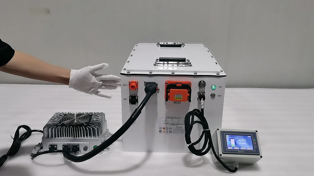
Charging is one of the most important parts of BMS integration.
Some battery systems use relatively simple charging arrangements. Others require continuous communication between the BMS and charger.
The correct design depends on the battery chemistry, charger capability, protection architecture, and application.
How does a BMS control charging through CAN?
In a communication-based charging system, the BMS may send information such as the maximum allowed charge voltage, maximum charge current, charging permission, and fault status.
The charger then uses that information to control its output.
For example, imagine a 96V-class lithium battery system with a charger capable of delivering 30 A.
Under normal conditions, the BMS may allow the full charging current.
As the battery approaches its upper voltage limit, the BMS may request a lower current.
If battery temperature becomes unsuitable for charging, the BMS may reduce the charge current limit further or stop charging according to the approved control strategy.
This coordinated approach helps avoid unnecessary protective shutdowns.
However, the charger must actually support the required control method.
A charger that only accepts a fixed voltage and current setting cannot be assumed to follow BMS CAN commands.
Why is pre-charge important?
Many electric vehicles and industrial battery systems use inverters or motor controllers with large DC-link capacitors.
Connecting a battery directly to these capacitors can create a high inrush current.
A properly designed pre-charge circuit limits this current before the main power path is fully connected.
Depending on the architecture, pre-charge may be controlled by the BMS, a power distribution unit (PDU), or another system controller.
The CAN network may be used to exchange pre-charge requests, status, permissions, or fault information.
However, CAN communication is not itself a pre-charge circuit.
The actual pre-charge hardware, timing, voltage checks, contactor ratings, and protection functions must be engineered separately.
Pre-charge resistor values and timing should be calculated from the real system requirements, not copied from an unrelated battery project.
What happens when CAN communication is lost?
Communication loss must be treated as a system design requirement.
Some systems may be able to continue operating for a limited period using a defined fallback strategy.
Others may need to reduce power or perform a controlled shutdown.
The appropriate behavior depends on the equipment and the consequences of losing battery status or operating limits.
For example, an electric vehicle should not continue demanding unrestricted power simply because the latest discharge limit message has disappeared.
Likewise, a charger should not assume that the last received current limit remains valid forever.
Engineers should define communication timeouts, safe operating states, fault recovery rules, and restart conditions.
CAN communication does not replace battery protection
The BMS must retain appropriate protection functions independently of normal CAN data exchange.
Depending on the system, these may include overvoltage, undervoltage, overcurrent, short-circuit, temperature, insulation, and other protective functions.
Communication can help the equipment operate within safe limits, but it should not be the only barrier against hazardous conditions.
For high-voltage batteries, contactor operation, insulation monitoring, interlocks, emergency shutdown functions, and electrical protection require system-level engineering.
These functions should be designed and validated by qualified personnel.
8. How to Integrate Multiple Lithium Batteries on One CAN Network
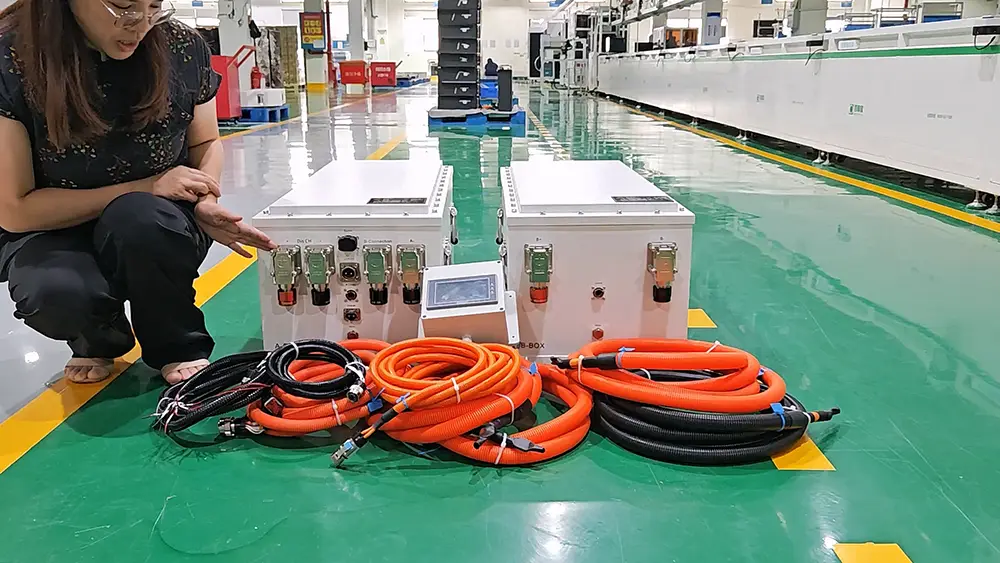
Using several battery packs in parallel can increase total capacity and available power.
However, multi-battery integration introduces additional communication and electrical challenges.
Consider a marine propulsion system using four battery packs connected in parallel.
The system may need to monitor every battery while presenting a single set of operating values to the propulsion controller.
This cannot always be achieved by connecting all BMS CAN wires together.
Individual BMS communication versus master-slave architecture
In some systems, each battery BMS operates as an individual CAN node with its own address.
The system controller receives information from every battery and calculates the overall battery bank status.
Other systems use a master-slave architecture.
The slave BMS units monitor individual battery modules, while a master controller manages communication and provides combined information to external equipment.
The correct architecture depends on the BMS design and system requirements.
| Integration Requirement | Why It Matters |
|---|---|
| Unique Node Addresses | Prevents message identification conflicts |
| Pack Voltage Monitoring | Helps verify operating compatibility |
| Individual Current Monitoring | Reveals current-sharing differences |
| Pack SOC Monitoring | Tracks battery conditions |
| Fault Coordination | Defines how the system responds to one pack fault |
| Combined Current Limits | Prevents external equipment from exceeding available power |
| Contactor Coordination | Manages safe connection and disconnection |
| Communication Timeouts | Detects missing or unresponsive battery modules |
Can the discharge current of all batteries simply be added together?
Not always.
Suppose four battery packs are each rated for 100 A continuous discharge.
It may be tempting to assume the complete bank can always deliver 400 A.
In practice, this depends on the cells, BMS settings, wiring resistance, temperature, SOC, current-sharing behavior, contactors, and protection architecture.
The available current may also change if one battery becomes unavailable.
For example, if one pack disconnects, the remaining packs must not automatically be expected to carry its share without a verified design.
The master controller or system control logic should manage the available power according to the actual condition of the battery bank.
CAN communication supports coordination, but it does not physically force current to divide equally between parallel batteries.
How should the system report total SOC?
A master BMS may calculate a combined SOC value for the complete battery bank.
However, simply averaging the SOC values of all packs may be inaccurate when packs have different usable capacities or operating conditions.
The aggregation method should reflect the actual battery architecture.
For OEM projects, it is important to confirm whether the external display or controller needs individual battery data, a combined battery status, or both.
9. BMS CAN Integration for EVs, Marine Batteries, AMRs, and Energy Storage
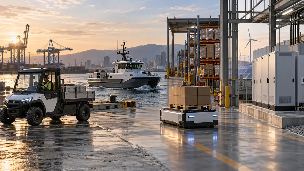
Different applications may use similar CAN hardware but require very different communication behavior.
This is why OEM battery projects should be evaluated around the complete equipment rather than selecting a BMS based only on voltage, current, or the presence of a CAN interface.
Electric vehicles and commercial EVs
In an electric vehicle, the BMS may communicate with the VCU, motor controller, charger, and vehicle display.
One important requirement is dynamic power limitation.
The BMS may report how much discharge or regenerative charging current the battery can safely accept under current conditions.
The VCU or motor controller must then use this information to manage vehicle operation.
Startup and shutdown sequencing, pre-charge, contactor control, and fault handling are also important.
For commercial vehicles and heavy equipment, SAE J1939 or manufacturer-specific CAN protocols may be required.
A custom EV battery project should therefore review the motor controller and VCU communication requirements before finalizing the BMS.
For related battery system engineering information, see our custom EV battery solutions ⇱.
Electric boats and marine propulsion systems
Marine battery integration can involve electric outboard motors, inboard propulsion controllers, onboard chargers, marine displays, and vessel monitoring systems.
A boat builder may want the battery to communicate with the propulsion system while also displaying SOC, voltage, current, and alarms on a multifunction display.
These may be two different communication requirements.
For example, the motor controller might use a proprietary CAN protocol, while the vessel display uses NMEA 2000.
In this situation, engineers must decide whether the battery needs separate communication interfaces or a suitable gateway.
They must also confirm the actual supported functions.
A gateway that translates basic battery status does not necessarily provide propulsion control or complete battery protection coordination.
Marine applications also require attention to moisture, corrosion, vibration, connector protection, and other environmental conditions.
Explore marine lithium battery systems ⇱ for more application-specific requirements.
AGV and AMR battery integration
Autonomous mobile robots (AMRs) and automated guided vehicles (AGVs) often operate with repeated charging and discharging cycles.
Some robots use automatic charging stations, while others use battery swapping or opportunity charging.
In these systems, the BMS may need to communicate with the robot controller and charging equipment.
Useful information may include SOC, voltage, current, temperature, charging permission, and fault status.
Sleep and wake-up behavior can also be important.
For example, the robot should not attempt to move if the battery is unavailable or in a protective state.
Similarly, an automatic charging system must coordinate its charging operation with the battery’s actual status.
For more information, see our custom AMR battery systems ⇱.
Industrial and commercial energy storage systems
In an energy storage system (ESS), the BMS may communicate with the PCS, energy management system (EMS), or inverter.
The communication architecture may include individual battery modules, a rack-level controller, and a system-level master BMS.
Common exchanged information includes SOC, voltage, current, temperature, charge and discharge limits, battery availability, and alarms.
For larger systems, communication between the rack BMS and system controller can be just as important as communication with the PCS.
The PCS must respond correctly to battery operating limits.
However, BMS-to-PCS communication is only one part of energy storage safety. Electrical protection, thermal management, emergency controls, and applicable system requirements still need separate verification.
10. Common BMS CAN Bus Problems and How to Fix Them
Even a well-designed CAN network can experience communication problems.
The fastest way to troubleshoot is to separate the problem into three areas: the physical network, message interpretation, and system control logic.
Trying to solve all three at once usually creates more confusion.
BMS CAN communication troubleshooting table
| Problem | Possible Cause | What to Check |
|---|---|---|
| No CAN messages received | Incorrect wiring or communication settings | CAN-H/L, pinout, baud rate, power |
| Communication works intermittently | Wiring, termination, noise, or supply problems | Cable layout, termination, grounding, error counters |
| CAN messages are visible but cannot be decoded | Wrong message definitions | CAN IDs, byte order, scale factors, DBC |
| SOC displays an incorrect value | Incorrect data conversion or signal mapping | SOC signal definition and scaling |
| Current value is negative when discharging | Different current sign convention | Protocol documentation |
| Charger does not start | Missing charging permission or handshake | Charger state machine and BMS conditions |
| Motor controller cannot start | Battery not ready or required messages missing | Startup sequence, permissions, status |
| Battery disconnects during operation | Protection event or control-sequence problem | BMS fault records and load profile |
| Communication stops after adding another battery | Address conflict or network configuration problem | Node IDs, bus loading, termination |
| Inverter receives SOC but does not follow limits | Unsupported or incomplete control integration | Required protocol, firmware, control settings |
| System reports CAN timeout faults | Missing or delayed periodic messages | Message cycle, timeouts, bus loading |
| Marine display shows no battery data | Missing NMEA 2000 compatibility | PGNs, network setup, device support |
The following examples illustrate how these problems may appear during real integration work.
Problem 1: The BMS sends data, but the controller does not respond
This often indicates a protocol mismatch rather than a physical CAN failure.
The BMS may be sending messages correctly, but the controller does not recognize the identifiers or data structure.
For example, a controller expecting an extended 29-bit CAN identifier may not interpret messages from a BMS using a different identifier format or application protocol.
Engineers should compare the protocol specifications before changing random communication parameters.
Problem 2: The charger starts but stops unexpectedly
This may happen when the charger and BMS do not agree on charging status or limits.
The charger might expect periodic permission messages that the BMS does not send.
Alternatively, the BMS may detect a charging condition outside its permitted range.
The correct investigation should include CAN logs, charger status, BMS alarms, and actual voltage and current measurements.
Increasing BMS protection limits simply to prevent shutdown is not an acceptable troubleshooting method.
Problem 3: Communication works on the bench but fails in the machine
A system may communicate correctly in a quiet laboratory but experience errors when installed near motor drives, high-current cables, or switching equipment.
Possible causes include electrical interference, unsuitable cable routing, grounding problems, poor connections, or incorrect network topology.
This is why actual equipment testing matters.
A CAN network should be evaluated under representative operating conditions, not only while the machine is standing still.
Problem 4: Adding more battery packs creates CAN errors
When several battery packs share one communication network, message identifiers and addressing must be coordinated.
If two BMS units transmit conflicting data using the same identifiers without a defined architecture, the receiver may not know which battery produced the information.
The system may also experience timing or network-loading problems.
Engineers should confirm the multi-battery communication design, not simply connect additional packs and assume they will work.
11. What Should OEMs Ask a Battery Manufacturer Before CAN Integration?
For OEM projects, the battery manufacturer should be involved in communication planning before the prototype is finalized.
A BMS that works well inside the battery may still require changes to communicate correctly with the customer’s equipment.
These changes may involve firmware, message mapping, interface wiring, system configuration, or additional control hardware.
The earlier these requirements are identified, the easier it is to avoid costly changes during testing.
BMS CAN integration checklist for OEM projects
| Requirement | Questions to Confirm |
|---|---|
| System Architecture | Which devices communicate with the battery? |
| CAN Hardware | Does the BMS support the required CAN interface and electrical isolation? |
| Baud Rate | What communication speed is required? |
| CAN Identifier Format | Does the equipment use 11-bit or 29-bit identifiers? |
| Communication Protocol | Is it proprietary CAN, J1939, CANopen, NMEA 2000, or another protocol? |
| Protocol Documentation | Are message definitions or DBC files available? |
| Battery Data | Which values must the BMS transmit? |
| Control Commands | Which commands must the BMS receive and support? |
| Charging | Does the charger require CAN communication or other control signals? |
| Protection Logic | What happens during faults and communication loss? |
| Multiple Batteries | Is master-slave control or a system controller required? |
| Software Changes | Can the BMS firmware be configured or customized? |
| Testing | Who is responsible for integration testing and approval? |
| Production Control | How are firmware versions and protocol changes managed? |
What documents should the battery manufacturer provide?
For a custom project, the documentation package may include a battery specification, CAN connector pinout, communication protocol, DBC file, message timing table, operating state description, and integration test plan.
The exact documents depend on the complexity and development stage.
If the protocol is proprietary, some information may be shared under an NDA.
The key requirement is that both engineering teams have enough information to verify compatibility.
What if the existing BMS protocol is incompatible?
There are several possible solutions.
The BMS firmware may be configurable to support the required messages.
In other cases, a different BMS or controller may be more suitable.
A communication gateway can sometimes translate between protocols, but it introduces additional requirements for timing, fault handling, and system validation.
A gateway should never be considered an automatic solution to every compatibility problem.
It also cannot fix electrical incompatibility, such as a battery voltage outside the equipment’s operating range.
Who should be responsible for integration testing?
Both the battery manufacturer and equipment OEM have responsibilities.
The battery manufacturer should verify the behavior of the supplied BMS and battery system.
The OEM or system integrator should verify how the complete equipment responds to that behavior.
For example, the battery manufacturer may confirm that the BMS correctly sends a reduced discharge current limit.
The OEM must then verify that the VCU or motor controller responds according to the agreed requirements.
A successful factory test of the battery alone cannot prove that the complete machine has been integrated correctly.
Don’t forget firmware version control
For repeat OEM orders, communication settings and firmware versions should be controlled.
A small firmware update may change message timing, fault behavior, or signal definitions.
If the battery manufacturer makes such changes without coordination, a previously working system may become incompatible.
The approved production configuration should therefore include relevant BMS hardware, firmware, protocol, and parameter versions.
When comparing suppliers, engineering support and change control can be just as important as battery price.
Our OEM guide to evaluating custom lithium battery manufacturers ⇱ explains other important supplier selection requirements.
Final Thoughts: Treat CAN Integration as Part of Battery Design
A reliable OEM battery system needs more than the right voltage, capacity, and discharge current.
It also needs to communicate correctly with the equipment using it.
The best approach is to confirm communication requirements early, select a suitable BMS, define the required messages and control behavior, and validate the complete system before production.
At Bonnen Battery, we work with OEM customers to evaluate custom lithium battery systems ⇱ around their electrical, mechanical, and communication requirements.
If you are developing an electric vehicle, marine propulsion system, industrial machine, AMR, or energy storage product, you can share your equipment specifications, controller model, CAN protocol, or communication requirements for an engineering review.
You do not need to have every detail finalized before starting the discussion.
However, providing the existing controller and charger documentation early can make the integration process much more efficient.
The goal is simple: deliver a battery that works with the equipment, not just a battery that looks correct on a specification sheet.
12. FAQs About BMS CAN Bus Integration
1. Can any lithium battery BMS with CAN bus work with my motor controller?
No. Having a CAN interface does not guarantee compatibility. The BMS and motor controller must use compatible communication settings, message identifiers, data formats, and control logic. Some controllers require specific messages for startup, discharge limits, or fault handling. Before selecting a BMS, request the controller’s communication protocol and confirm whether the battery manufacturer can support it.
2. How do I connect a lithium battery BMS to a CAN bus network?
Start by checking the BMS and equipment communication pinouts. Connect CAN-H and CAN-L according to the manufacturers’ instructions, and verify the required grounding, isolation, termination, and network configuration. The devices must use compatible communication settings and protocols. After connecting the network, use suitable diagnostic equipment to verify message transmission before testing actual system operation.
3. What CAN baud rate should I use for a battery BMS?
The correct baud rate depends on the BMS and connected equipment. Common Classical CAN speeds include 125 kbps, 250 kbps, and 500 kbps, but these are not universal settings. Every device on the same CAN network must use compatible bit timing. Check the equipment documentation rather than choosing a speed based only on what is commonly used in another application.
4. Does a BMS CAN bus need a 120-ohm termination resistor?
A typical high-speed CAN network requires a 120-ohm termination resistor at each physical end of the bus. With two correctly installed resistors, the resistance between CAN-H and CAN-L is normally about 60 ohms under suitable powered-down measurement conditions. However, some devices include internal termination resistors, so additional resistors may not be necessary. Always check the actual network design and manufacturer instructions.
5. Why can my motor controller receive CAN messages but not read the BMS data correctly?
The physical CAN network may be working while the message definitions are incompatible. Possible causes include incorrect CAN IDs, byte order, data scaling, signal positions, or frame formats. For example, the controller might expect battery current in a different unit or sign convention. Compare the BMS protocol with the controller’s requirements and use a CAN analyzer or DBC file to check the decoded values.
6. What is a BMS DBC file, and do I need one for integration?
A DBC file describes CAN messages and how to decode their data into useful values such as battery voltage, current, temperature, and SOC. It is helpful when developing software, configuring controllers, or troubleshooting communication. However, a DBC file may not describe the complete control process. For complex OEM systems, you may also need documentation covering startup, charging, contactors, timeouts, and fault handling.
7. Can a lithium battery BMS communicate with a charger through CAN bus?
Yes, if both the BMS and charger support a compatible communication protocol. The BMS may send charging voltage limits, current limits, charging permission, and fault information. The charger must interpret these messages and adjust its output correctly. Some chargers use fixed voltage and current settings instead of CAN communication, so compatibility must be confirmed for the specific charger model.
8. Can a BMS use SAE J1939 communication for a commercial vehicle?
Yes, some BMS platforms support SAE J1939 or can be configured for selected J1939 communication requirements. However, support for J1939 does not mean every vehicle-specific message is available. OEM engineers must check the required PGNs, SPNs, addressing, timing, and control behavior. The BMS should be tested with the actual VCU or vehicle controller before production approval.
9. Can a BMS communicate directly with a Victron Cerbo GX?
Some compatible battery systems can communicate with a Victron Cerbo GX through the appropriate CAN interface. However, the battery must support a compatible protocol, connection method, and operating configuration. Victron also has specific requirements for supported third-party batteries, port profiles, cables, and firmware. Check the exact battery and Victron equipment models before assuming compatibility.
10. Is BMS CAN bus the same as NMEA 2000?
No. NMEA 2000 uses CAN technology, but it defines additional communication and network requirements for marine equipment. A standard BMS CAN interface does not automatically support NMEA 2000 messages or device behavior. To communicate with an NMEA 2000 display, the system needs an appropriate and compliant implementation. This may require dedicated BMS support or a suitable certified gateway.
11. Can a lithium battery send SOC and voltage directly to a Simrad or Garmin display?
It may be possible if the battery system provides compatible NMEA 2000 data through an appropriate interface. However, the display and battery must support the required messages and configuration. CAN communication alone is not enough. Before developing a marine system, confirm which battery values the display can show and whether the proposed interface meets the applicable NMEA 2000 requirements.
12. Can multiple lithium batteries share the same CAN bus network?
Yes, if the battery system is designed for multi-node communication. Each battery may need a unique address, or the system may use a master-slave architecture. Engineers must also define how battery status, current limits, warnings, and faults are managed. Connecting several independent BMS units to one CAN network without proper configuration may cause address conflicts or incorrect data reporting.
13. How does a master BMS communicate with slave BMS units?
In a master-slave battery architecture, individual slave BMS units monitor their assigned modules or battery packs. A master controller collects relevant information and may coordinate system-level functions. It can also communicate combined battery information to external equipment. The exact communication method and responsibilities depend on the BMS manufacturer and battery architecture. Some systems use CAN internally, while others use different interfaces.
14. What happens if CAN communication is lost while the battery is operating?
The response depends on the system’s safety design. A controller may reduce power, stop charging, issue a warning, or enter a defined safe operating state. The BMS may also activate protection functions if required information or operating conditions become unsafe. Engineers should define message timeouts and fault responses during development. Communication loss should never leave the system with undefined operating permissions.
15. Can CAN bus control battery contactors and pre-charge?
CAN messages can be used to request or coordinate contactor and pre-charge operations when the system supports those functions. However, the actual electrical operation depends on dedicated hardware and approved control logic. A CAN message alone cannot safely charge an inverter’s DC-link capacitors or replace contactor protection. Pre-charge, interlocks, feedback, and fault handling must be designed and tested as part of the complete power system.
16. Why does my BMS show the wrong current value over CAN?
An incorrect current reading may result from a wrong scale factor, byte order, data type, or sign convention. For example, one system may report positive current during charging while another uses positive current during discharging. The BMS measurement itself may also need investigation. Compare the CAN protocol with an independent measurement and verify the signal definition before changing controller software or BMS settings.
17. Can I customize the BMS CAN communication protocol for an OEM project?
In many cases, yes, but it depends on the BMS hardware, firmware access, manufacturer support, and project requirements. Some BMS products allow configuration of CAN IDs, data mapping, or transmission periods. Others use fixed protocols. More advanced customization may require firmware development or a different BMS platform. OEM customers should confirm customization capability before ordering prototypes.
18. How do I test BMS CAN communication before mass production?
Begin with protocol and wiring verification, then check actual message transmission using a CAN analyzer. Confirm signal accuracy, message timing, commands, and operating permissions. Next, test the complete equipment under representative conditions, including charging, discharging, startup, shutdown, and fault handling. The battery manufacturer and OEM should agree on measurable acceptance criteria and maintain records of the approved integration configuration.
19. Is CAN bus better than RS485 for lithium battery communication?
Neither interface is automatically better for every application. CAN is widely used in vehicles and industrial control networks because it supports multi-node communication, message arbitration, and built-in error detection. RS485 provides a robust differential physical interface and is often used with protocols such as Modbus RTU. The best choice depends on the existing equipment, protocol requirements, network architecture, and operating environment.
20. What information should I send a battery manufacturer for BMS CAN integration?
Start with the equipment application, battery voltage range, required power, controller model, charger model, and communication interface details. If available, provide the CAN protocol document, DBC file, connector pinout, required battery messages, and operating sequence. It is also useful to explain whether you need charging control, contactor coordination, remote monitoring, multiple-battery operation, or special fault handling. These details help the manufacturer evaluate compatibility and define the development work.
Technical References and Further Reading
The following resources provide additional technical information about CAN communication, battery interfaces, and relevant industry protocols.
CAN Bus Fundamentals: CSS Electronics — CAN Bus Explained explains CAN frame structures, identifiers, message decoding, and network fundamentals.
CAN Termination: Kvaser — How to Test Your CAN Termination provides practical information about termination resistors and network measurements.
DBC Files: CSS Electronics — CAN DBC File Explained explains how CAN databases are used to interpret raw messages.
J1939 Communication: CSS Electronics — J1939 Explained introduces PGNs, SPNs, and communication structures used in heavy-duty equipment.
CANopen: CAN in Automation — CANopen Lower Layers provides technical information about CANopen communication requirements.
Marine Communication: NMEA — NMEA 2000 Standards explains the marine network standard, supported application areas, and certification requirements.
Victron Compatibility: Victron Energy — Connecting Supported Non-Victron Products provides official guidance on supported third-party battery communication.
Contact Bonnen Battery↓ now and let us help you power your adventures with the best lithium battery technologies.
© [Bonnen Battery] and [www.bonnenbatteries.com]. Unauthorized use and/or duplication of this material without express and written permission from this site’s author and/or owner is strictly prohibited. Excerpts and links may be used, provided that full and clear credit is given to [Bonnen Battery] and [www.bonnenbatteries.com] with appropriate and specific direction to the original content.