
Custom EV Battery Systems
EV Battery Systems Engineered Around Your Vehicle
Custom low-voltage and high-voltage lithium battery systems for EV conversions, commercial electric vehicles, and specialty EV platforms - developed around your voltage, power, driving range, installation space, charging, and communication requirements.
Start with your vehicle, motor, target range, or available space. Incomplete information is enough to begin.
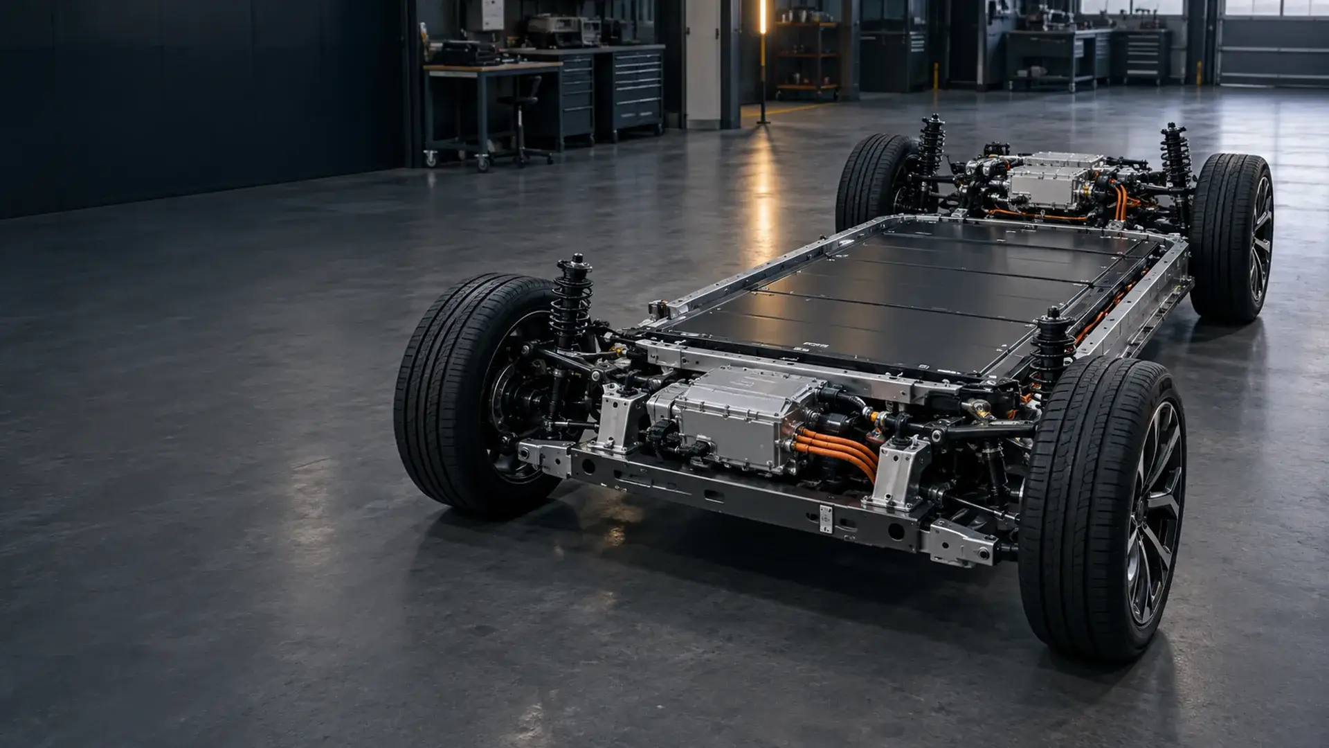
Voltage
Low- and high-voltage development matched to the vehicle and duty cycle.
Packaging
Enclosures, mounting, interfaces, and pack layout developed around available space.
Communication
BMS, VCU, charger, and CAN requirements reviewed as one vehicle system.
Production
Engineering support from initial architecture through pilot and batch production.
Vehicle-First Engineering
Your EV Battery Starts With the Vehicle - Not a Catalog
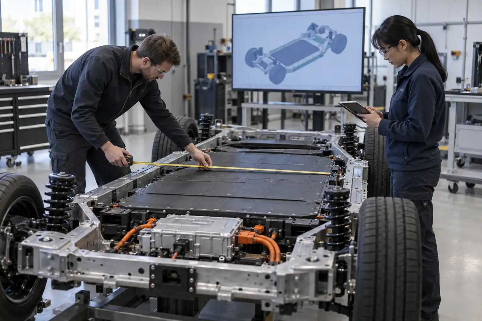
Two vehicles can share the same nominal voltage and still need completely different battery systems. Motor power, controller current, driving range, payload, installation space, charging, communication, temperature, and validation targets all influence the final architecture.
We begin with the vehicle and duty cycle, then define the battery voltage, usable energy, current capability, chemistry, enclosure, thermal strategy, BMS, protection components, and interfaces.
- Motor rated and peak power
- Controller maximum current
- Vehicle operating voltage
- Target range or operating time
- Vehicle weight and payload
- Available battery envelope
- Charging voltage and power
- CAN or VCU communication
- Operating temperature
- IP, vibration, and shock requirements
Application Fit
EV Platforms We Support

EV Conversions
Classic cars, passenger vehicles, and prototype conversions fitted around an existing chassis.
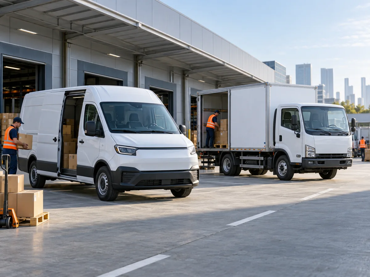
Commercial Electric Vehicles
Electric vans, delivery vehicles, and light trucks where range, payload, duty cycle, and serviceability interact.
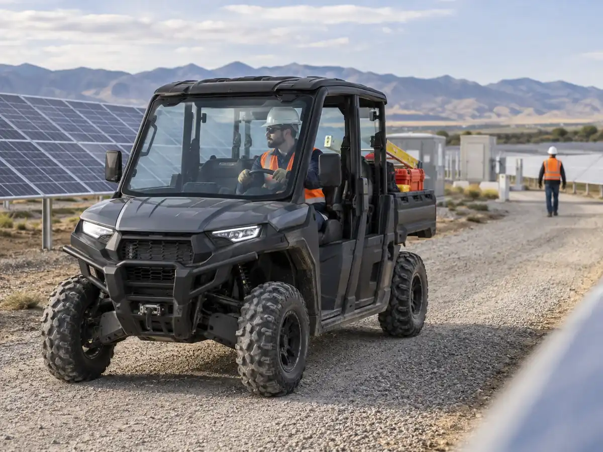
UTV Electric Vehicles
Electric utility terrain vehicles for industrial sites, agriculture, estates, and field-service operations.
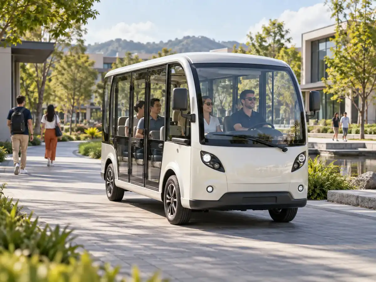
Low-Speed EV Platforms
LSVs, patrol vehicles, and sightseeing vehicles that need compact, repeatable integration.
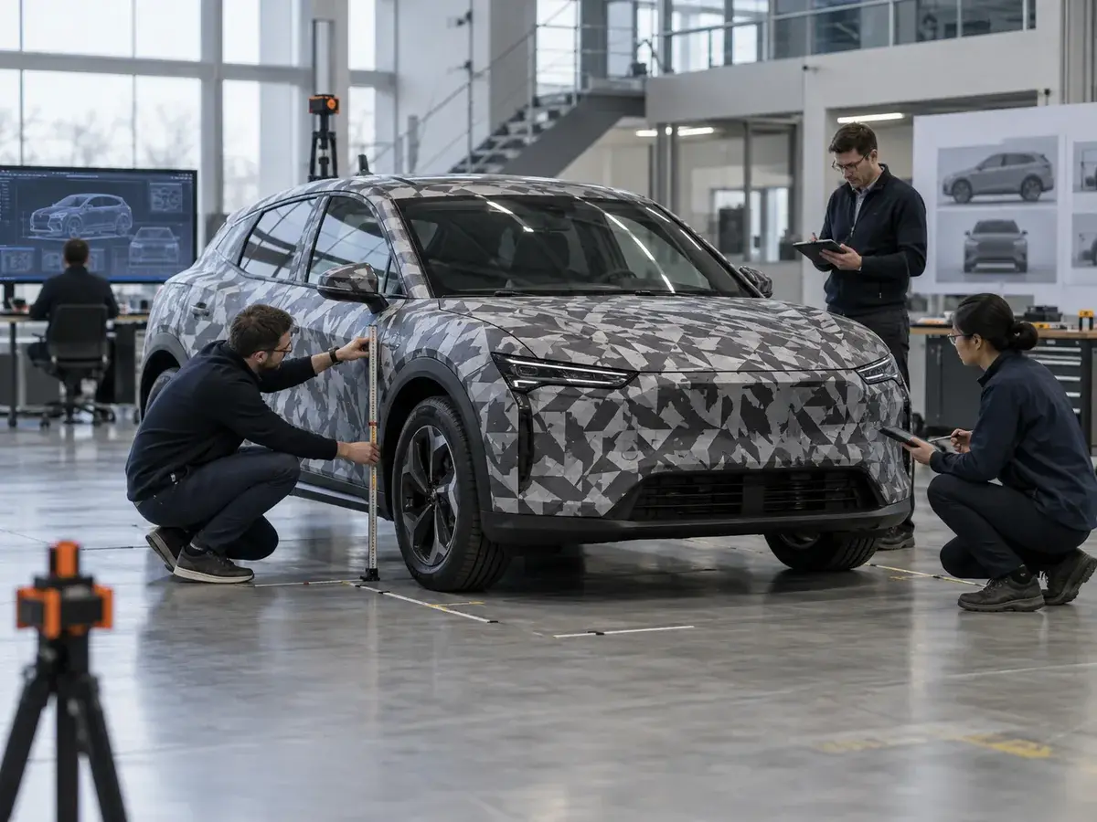
Custom OEM EV Platforms
New vehicle programs, pilot projects, and low-volume production with coordinated system development.
Architecture Range
From Low-Voltage EVs to High-Voltage Vehicle Platforms
48V-144V
Conversion and Utility Platforms
EV conversions, low-speed EVs, utility EVs, and specialty vehicles.
200V-450V
Passenger and Light Commercial
Passenger EVs, electric vans, light-commercial vehicles, and custom OEM programs.
450V-700V+
High-Power Vehicle Platforms
Commercial vehicles, high-power EV platforms, and special-purpose vehicles.
LFP
Often evaluated when thermal stability and cycle-life potential are important for commercial, utility, or conversion projects.
NMC
Often evaluated when higher energy density is important for space- or weight-sensitive packaging.
Chemistry selection remains project-dependent and is reviewed against packaging, power, thermal, service-life, and market requirements.
System Integration
Built Around Your Vehicle Architecture
The battery is developed as part of the vehicle system, not as an isolated enclosure.
Electrical Design
Nominal and operating voltage, usable energy, continuous and peak current, motor and inverter compatibility, and charging power.
Mechanical Integration
Dimensions, orientation, mounting points, chassis interfaces, connector positions, weight distribution, and enclosure layout.
Controls and Communication
BMS architecture, CAN 2.0 or J1939 where required, VCU and charger integration, SOC/SOH reporting, and fault logic.
Environmental Design
Ingress protection, temperature, air or liquid thermal management, heating, vibration, shock, pressure relief, and sealing.
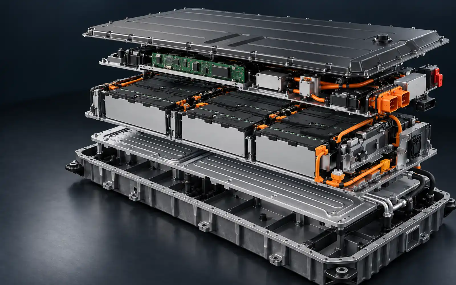
System Anatomy
More Than Cells in a Box
A complete EV battery system coordinates energy storage, switching, protection, communication, thermal paths, service access, and the vehicle interface.
Engineering Starting Points
Representative EV Battery Configurations
Low-voltage
96V EV Conversion System
- 96V-class architecture
- LFP or NMC according to project priorities
- Custom enclosure and connector layout
- Current matched to motor and controller
- Single- or split-pack layouts where required
High-voltage
300V-400V Vehicle Battery System
- Integrated HV protection components
- CAN communication
- Thermal management matched to duty cycle
- Passenger and light-commercial EV development
High-power
500V-700V+ High-Voltage System
- High continuous and peak power capability
- Liquid cooling where required
- HVIL, MSD, fuse, and contactor integration
- Commercial and high-power EV platforms
These are representative engineering configurations, not fixed catalog products. Final voltage, capacity, current capability, thermal system, and enclosure are developed around each vehicle project.
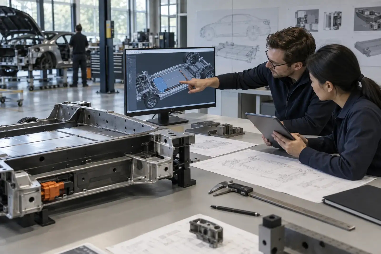
Project Inputs
Start With What You Know
You do not need a complete battery specification to start.
- Vehicle type and application
- Motor rated and peak power
- Motor and controller voltage
- Controller maximum current
- Target range or operating time
- Battery installation space
- CAD or STEP files
- Maximum battery weight
- Charging requirements
- Operating environment
- Prototype and annual quantity
Incomplete information is OK. Our engineers can help define the remaining battery parameters.
Send Your Vehicle RequirementsVerified Project Cases
EV Battery Development in Practice
Customer identities are withheld. Details are limited to the project information supplied for this page.
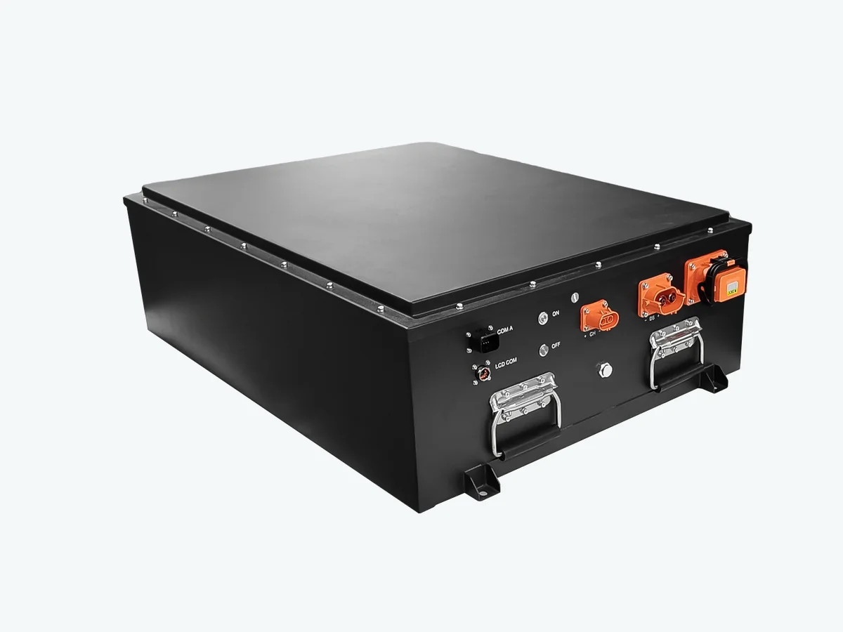
96V Classic-Car Conversion
- Constraint
- Compact packaging for an existing vehicle with repeatable dimensions and interfaces.
- Engineering response
- Vehicle-led enclosure, cell configuration, BMS protection, high-current connections, and mounting design.
- Project stage
- Progressed beyond prototype development into repeat batch supply.
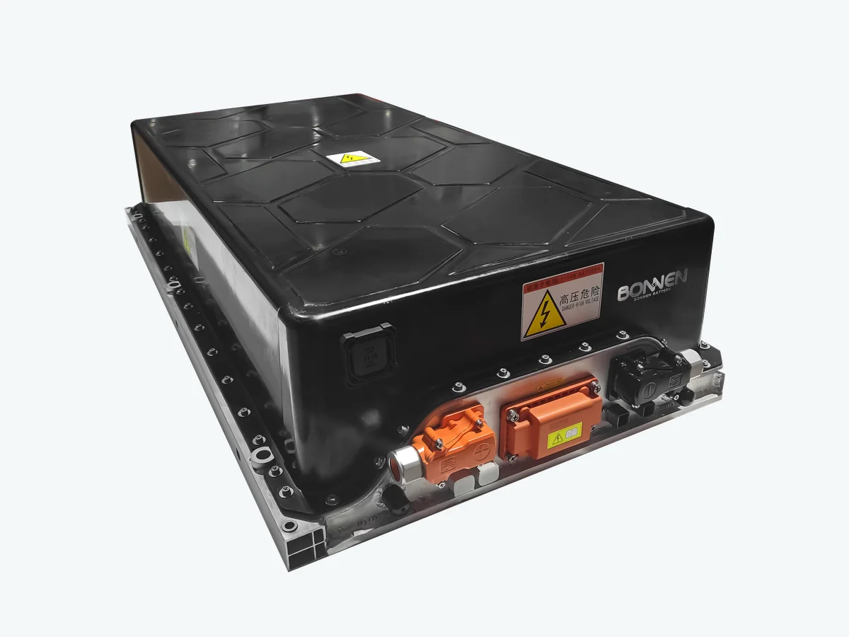
332.8V Vehicle Battery System
- Constraint
- Energy and power within a fixed space while integrating inverter, charger, communications, and HV safety.
- Engineering response
- Integrated modules, BMS, HV protection, service disconnect, communication, thermal management, and vehicle connections.
- Project stage
- Completed engineering and validation and progressed into batch production.
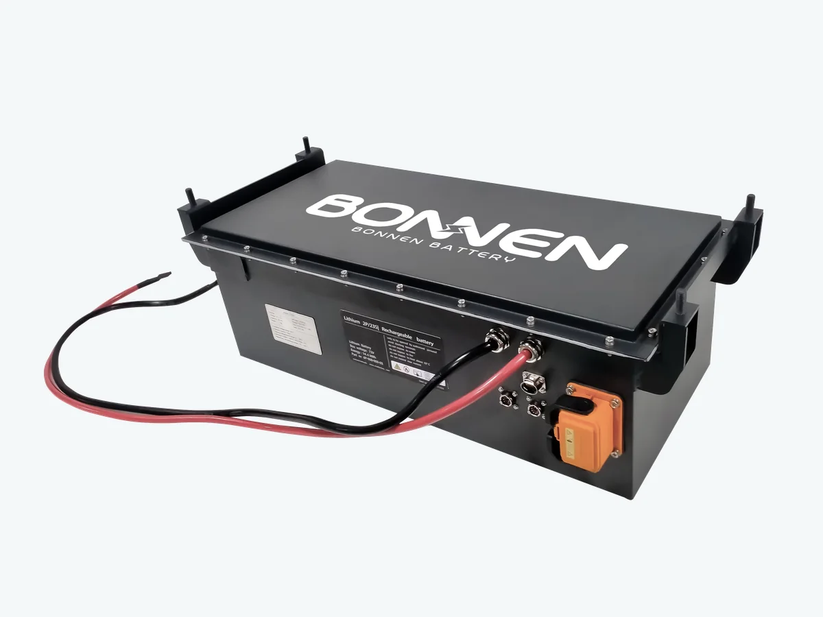
72V Tuk-Tuk and Electric Tricycle
- Constraint
- Frequent daily use, repeated cycling, high ambient temperature, vibration, and a compact chassis envelope.
- Engineering response
- A robust 72V pack with BMS protection, high-current output, thermal design, and repeatable interfaces.
- Project stage
- Completed vehicle integration and validation and progressed into ongoing batch production.
Development Path
From Vehicle Requirements to Production Battery
- 01
Requirement Review
Vehicle, motor, inverter, range, packaging, environment, charging, communication, and volume inputs.
- 02
Battery Architecture
Voltage, energy, chemistry, current capability, BMS strategy, and protection concept.
- 03
Mechanical Integration
Cell or module layout, enclosure, mounting, service access, and connector positions.
- 04
Electrical and Thermal Design
HV protection, communication, cooling, heating, and the charging interface.
- 05
Prototype Manufacturing
Prototype pack build in the agreed configuration for vehicle integration work.
- 06
Validation
Applicable electrical, insulation, communication, thermal, sealing, vibration, and enclosure checks.
- 07
Pilot Production
Small-batch verification of build, inspection, and integration repeatability.
- 08
Batch Production
Controlled production, inspection, documentation, and delivery after project release.
Build and Verify
EV Battery Manufacturing and Validation
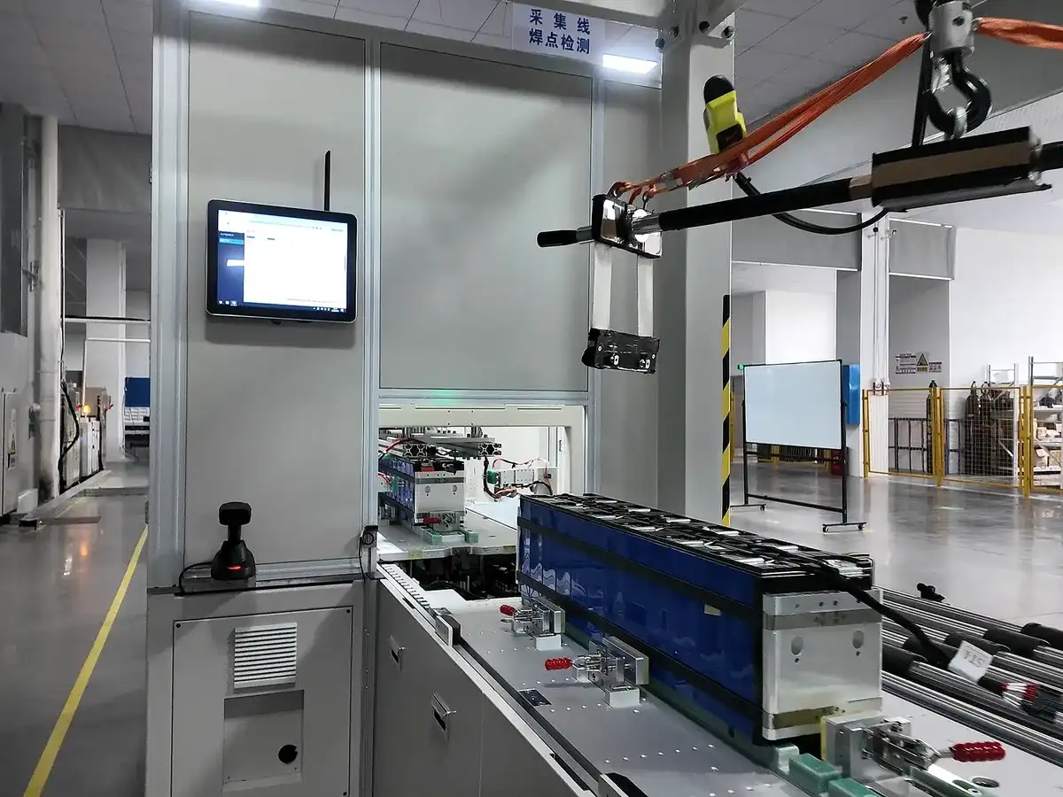
Module Production
Cell and module processes are completed according to the released design and selected components.
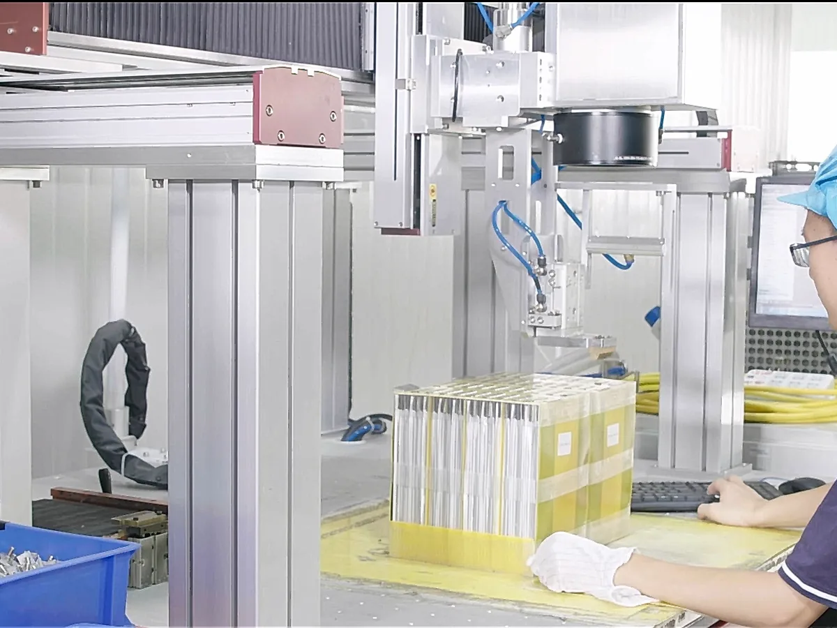
Joining and Integration
Joining and electrical interfaces follow the process specified for the cells, busbars, modules, and enclosure.
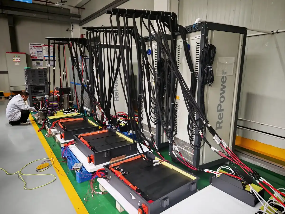
Electrical Functional Testing
Electrical checks verify the released configuration and applicable pack functions before delivery.
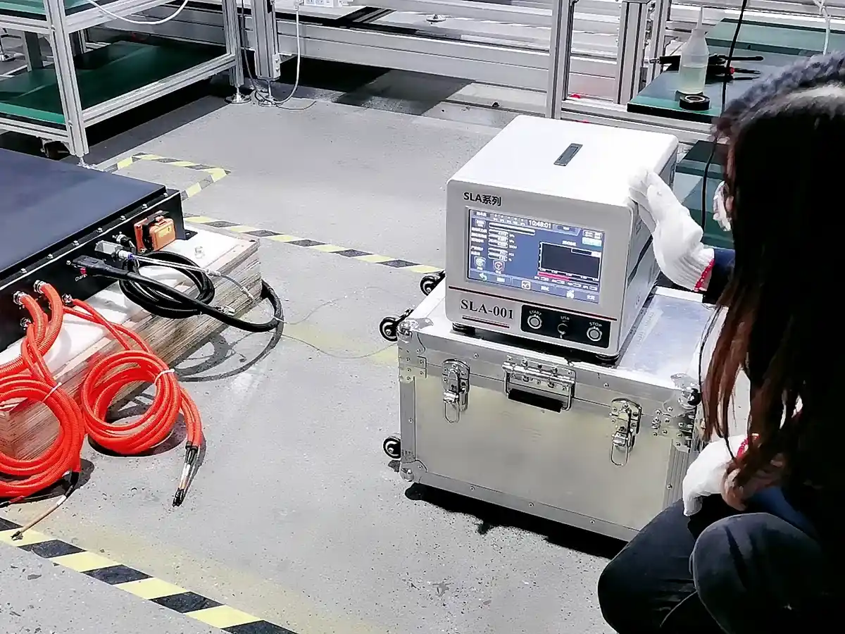
Pack Sealing Checks
Airtightness and enclosure sealing checks are applied where required by the project validation plan.
Global Project Support
Documentation and Compliance Support for Global EV Projects
Depending on the final design and destination, project documentation may include UN38.3 transport test documentation, MSDS, dangerous-goods shipping documents, quality-management evidence, and support for CE, IEC, or CB requirements where applicable.
Documentation and certification requirements are reviewed according to the final battery design, vehicle category, and destination market.
- 01Transport and shipping documentation
- 02Quality-management evidence
- 03Market-specific requirement review
- 04Project-level test and document planning
Compliance support does not mean every battery configuration carries the same approvals. Applicable standards, test scope, document ownership, and market requirements must be confirmed during the project.
FAQs About Custom EV Battery Systems
Practical answers for EV manufacturers, vehicle conversion companies, system integrators and engineering teams developing custom lithium battery systems for electric vehicles.
Begin With Your Vehicle
Tell Us About Your EV Project
Share your motor voltage, power, target range, available battery space, or vehicle CAD. Even incomplete project information is enough to start.
Get an EV Battery ProposalInclude your vehicle type, motor or inverter data, available space, charging needs, operating environment, and expected quantity if known.