Last Updated on 10/10/2026 by Bonnen Battery
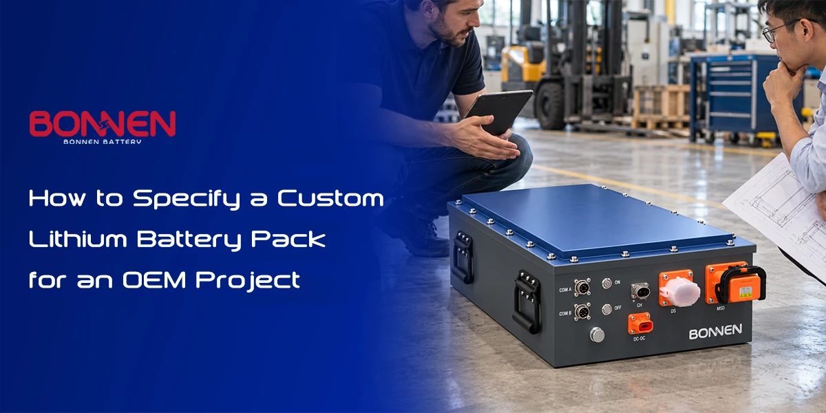
How to Specify a Custom Lithium Battery Pack for an OEM Project
A custom lithium battery pack should not be specified by voltage and capacity alone. For an OEM project, the correct starting point is the equipment: its operating voltage range, power demand, peak current, runtime, available battery space, charging method, working temperature, communication interface, safety requirements, target market, and expected production volume. The battery manufacturer can then turn those requirements into the right cell chemistry, series-parallel configuration, BMS, thermal system, enclosure, connectors, and validation plan.
In simple terms, an OEM should define what the machine needs the battery to do before deciding what the battery should look like.
This approach avoids one of the most common mistakes in custom battery projects: choosing a cell or battery capacity first and trying to make the equipment fit around it later.
A useful custom battery specification therefore answers four basic questions: How much energy does the equipment need? How much power must the battery deliver? Where and under what conditions will it operate? How will the battery communicate, charge, and connect to the rest of the system?
This guide explains how to answer those questions and turn them into a practical battery specification that a battery engineering team can actually design around.
1. What Does “Specifying a Custom Lithium Battery Pack” Really Mean?
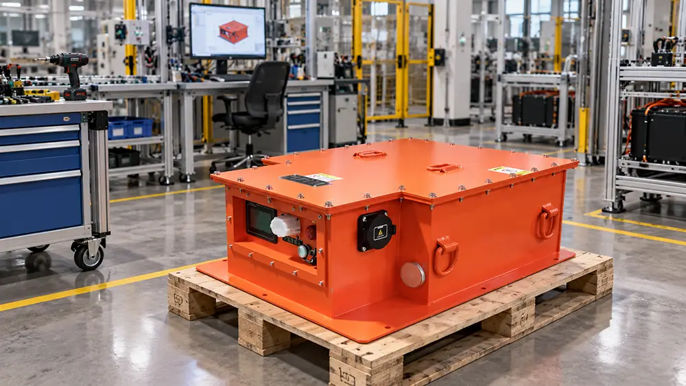
A battery specification is not simply a product description. It is a set of electrical, mechanical, environmental, communication, safety, and commercial requirements that defines how the battery must work inside the final equipment.
For an OEM project, these requirements are connected.
For example, increasing battery capacity may increase runtime, but it also increases weight, enclosure size, cell quantity, cost, and charging time. Increasing discharge current may require higher-power cells, larger busbars, different contactors, larger cables, better cooling, and a higher-current BMS.
That is why specifications such as “96V 200Ah lithium battery” are usually not enough to start a serious custom project.
A better starting specification looks like this:
| Requirement | Example Information |
| Application | Electric utility vehicle |
| System voltage | 96V nominal |
| Motor | 15kW |
| Continuous battery current | 160A |
| Peak current | 350A for 10 seconds |
| Required operating time | 4 hours per shift |
| Maximum battery space | 950 × 600 × 300 mm |
| Maximum weight | 180 kg |
| Operating temperature | -10°C to 45°C |
| Charging | 3.3kW onboard charger |
| Communication | CAN with vehicle controller |
| Protection | Outdoor, IP67 target |
| Prototype quantity | 1 pack |
| Annual demand | 50–100 packs |
| Destination market | European Union |
–
This gives a battery engineer something useful to work with.
A good rule is:
The OEM should specify the equipment requirement; the battery supplier should translate that requirement into the battery architecture.
Have a Project but Not a Complete Battery Specification?
You do not need to know the exact cell model, BMS model, or series-parallel configuration before contacting us. Send us your application, voltage, motor or load power, runtime, maximum battery dimensions, operating environment, and expected quantity. We can use those requirements to begin the battery feasibility study.
2. Start With the Machine, Not the Battery
The first question should not be “Which battery do you want?”
It should be “What does the equipment need to do?”
An electric boat operating for six hours at moderate load has a very different battery duty cycle from heavy equipment battery systems ⇱ used in mining or construction machines that repeatedly accelerate, lift, or operate hydraulic loads. An AGV working around the clock with opportunity charging has different priorities from an electric vehicle battery system ⇱ designed mainly around overnight charging.
Duty cycle means the pattern of power demand, operating time, rest time, charging, and environmental conditions that a battery experiences during normal use.
For battery engineering, a duty cycle is often more useful than the motor nameplate alone.
Consider two machines that both use a 20kW motor. One may normally operate at 5kW and reach 20kW only for a few seconds. The other may run close to 18kW for long periods.
They should not automatically use the same battery.
Before discussing cells, the OEM should therefore describe how the equipment works in the real world.
Useful information includes average operating power, maximum power, typical operating hours per day, acceleration or hydraulic load peaks, regenerative braking, idle periods, charging opportunities, number of shifts, and expected service life.
When possible, real current-versus-time data from an existing machine is especially valuable.
This reflects a broader principle used in battery lifetime modeling: battery degradation depends on factors such as charge and discharge rates, temperature, state-of-charge history, storage conditions, and cycling patterns rather than on capacity alone. NREL specifically considers these factors when modeling real-world battery lifetime.
3. Specify the Voltage Window, Not Just the Nominal Voltage
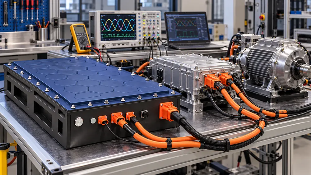
“48V,” “72V,” and 96V battery systems ⇱ are useful voltage classifications, but these labels alone are not complete electrical specifications.
Lithium battery voltage changes with state of charge, load, chemistry, and cell configuration.
The equipment therefore needs to tolerate the battery’s full operating voltage window.
For example, an OEM should confirm:
| Voltage Item | Why It Matters |
| Nominal voltage | General system classification |
| Maximum battery voltage | Must be accepted by inverter, controller and charger |
| Minimum operating voltage | Equipment must continue operating before BMS low-voltage protection |
| Charger output voltage | Must match the battery charging profile |
| Regenerative voltage | Must remain inside the battery’s safe charging window |
–
The most important compatibility question is not “Is this a 96V motor?”
It is:
Can every connected component safely operate between the battery’s minimum and maximum system voltage?
This includes the inverter, motor controller, DC/DC converter, onboard charger, contactors, fuses, display, pre-charge circuit, and auxiliary equipment.
Voltage also affects current.
For the same power:
Current (A) = Power (W) ÷ Voltage (V)
A 20kW load at 100V theoretically requires about 200A.
The same 20kW load at 400V requires about 50A.
Actual current can be higher because of inverter efficiency, voltage sag, auxiliary loads, acceleration, and changing battery voltage.
For this reason, current calculations should not rely only on nominal voltage.
4. Define Energy and Runtime in kWh, Not Only Ah
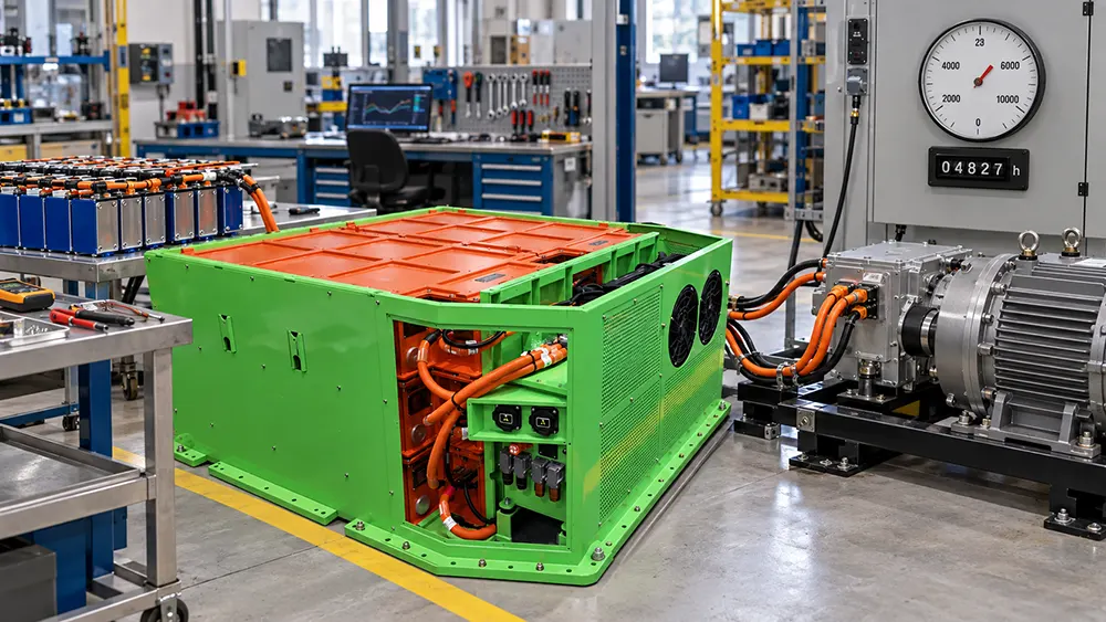
Amp-hours tell only part of the story.
Energy is normally more useful when comparing battery systems at different voltages.
The basic relationship is:
Battery Energy (Wh) = Nominal Voltage (V) × Capacity (Ah)
For example:
96V × 200Ah = 19,200Wh
That is approximately 19.2kWh of nominal energy.
But nominal energy is not automatically usable energy.
The machine may stop operating before the battery reaches 0% SOC. The BMS may reserve part of the SOC range, and system losses also reduce useful output.
A practical early-stage runtime estimate is:
Required Battery Energy = Average Equipment Power × Required Runtime ÷ Expected Usable Energy Ratio
Suppose an electric machine averages 5kW and needs to work for three hours.
Its load requires about:
5kW × 3h = 15kWh
If the project assumes only 85% of nominal pack energy should be used during normal operation, the theoretical battery requirement becomes:
15kWh ÷ 0.85 = 17.65kWh
Additional engineering margin may still be needed for aging, cold-weather performance, accessories, and unexpected load conditions.
This is why asking only for “200Ah” can be misleading. A 200Ah battery at 48V contains roughly half the nominal energy of a 200Ah battery at 96V.
For OEM projects, specify both Ah and kWh whenever possible.
5. Continuous Current, Peak Current and Peak Duration Must Be Separated
One of the most important parts of a custom battery specification is the load profile.
Battery current should usually be divided into continuous current and peak current.
Continuous current is the current the battery can supply for a sustained operating period within its thermal and electrical limits.
Peak current is a higher current allowed for a limited duration, such as acceleration, lifting, starting a pump, climbing a slope, or operating a winch.
Peak current without peak duration is an incomplete specification.
“500A peak” could mean 500A for one second, 10 seconds, 30 seconds, or several minutes. Those conditions can require very different cells, busbars, contactors, thermal designs, and BMS settings.
C-rate is another useful way to describe battery current.
A 1C discharge rate means a current equal to the battery’s Ah capacity.
For a 200Ah battery:
1C = 200A
2C = 400A
However, a cell’s C-rate should never be assumed from chemistry alone. It should be confirmed against the actual cell manufacturer’s specification and operating conditions.
For motor-driven equipment, a useful first estimate is:
Battery Current = Electrical Power ÷ Battery Voltage
But the final specification should come from controller data, system measurements, or a detailed load profile whenever possible.
In one industrial winch project we worked on, the motor voltage and rated power initially looked like enough information. Once balance, battery weight, installation height, continuous current, and the need for two batteries in parallel were considered together, the final pack architecture became very different from the first concept.
That is a common pattern in OEM development: one parameter rarely decides the pack.
6. Choose Battery Chemistry After the Requirements Are Clear
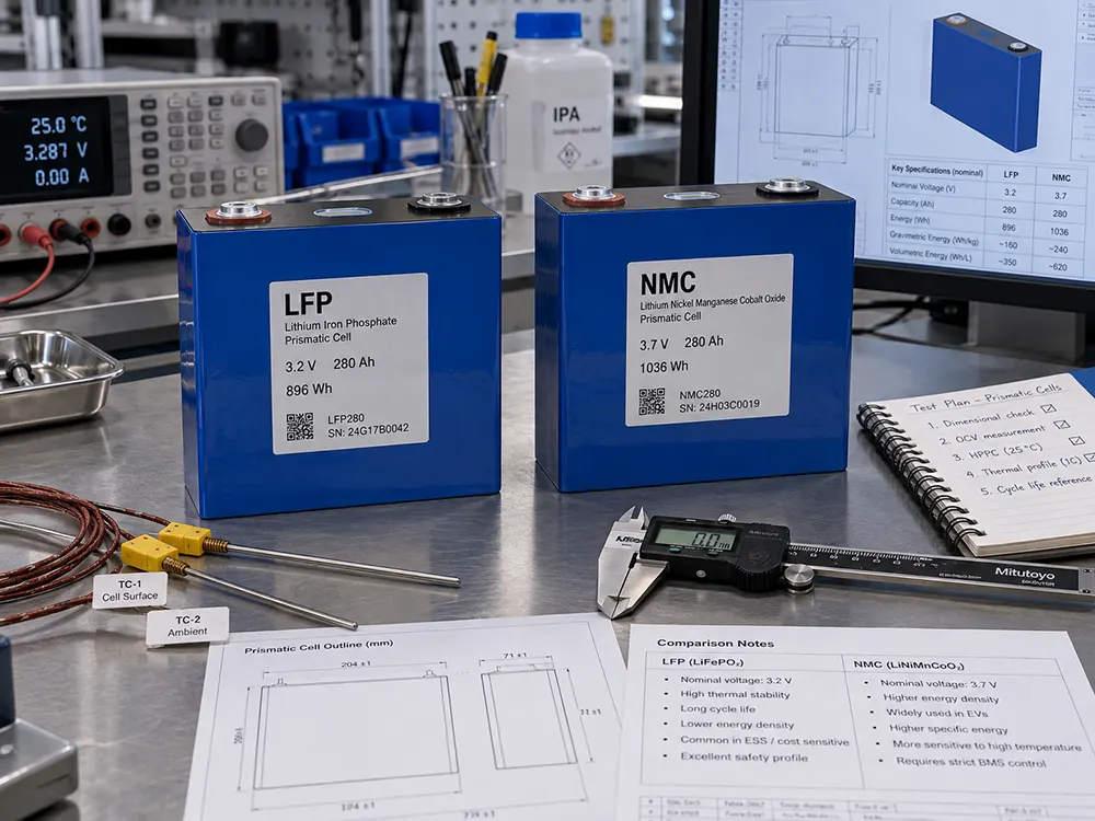
For many OEM battery projects, lithium iron phosphate (LFP) and nickel manganese cobalt (NMC) are the main chemistry choices.
Neither is automatically “better.”
LFP is often selected when battery lifespan and cycle life ⇱, thermal stability, cost control, and frequent cycling are important.NMC is often considered when weight and installation volume are especially limited.
Published reviews generally show the same basic trade-off: NMC offers higher gravimetric energy density, while LFP generally provides strong cycle life and thermal stability. Exact values depend heavily on the specific cell design, manufacturer, temperature, charge rate, discharge rate, and test method.
| Design Priority | LFP | NMC |
| Energy density | Moderate | Higher |
| Cycle-life potential | High | Moderate to high |
| Thermal stability | Strong | Requires closer thermal control |
| Weight-sensitive designs | Possible | Often advantageous |
| Daily industrial cycling | Very suitable | Application dependent |
| Compact EV or marine installation | Possible | Often attractive |
–
The cell format also matters.
Large prismatic cells may reduce the total number of cells and interconnections. Cylindrical cells can offer design flexibility and good thermal characteristics but may require many parallel connections. Pouch cells can provide strong packaging efficiency but require careful mechanical compression and protection.
The correct question is not:
“What is the best lithium cell?”
It is:
“Which cell can meet this project’s energy, power, temperature, packaging, lifetime, availability, and safety requirements at the same time?”
7. Mechanical Design Is Part of the Battery Specification
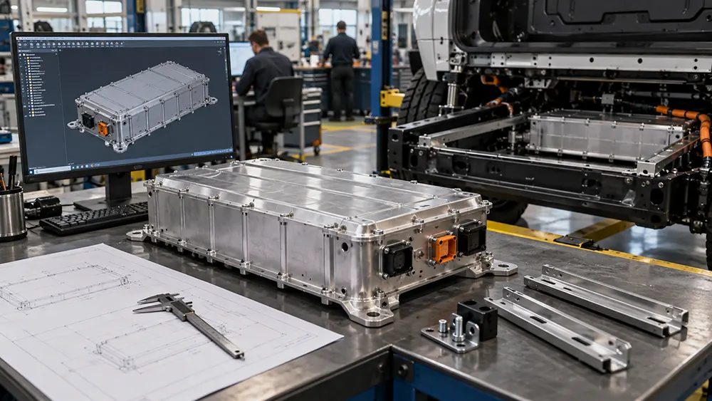
Maximum battery dimensions are only the beginning of lithium battery enclosure design ⇱ and mechanical integration.
The engineering team also needs to know where cables exit, where connectors can be accessed, how the pack is installed, whether it must be removed for service, how much clearance exists around the enclosure, and where the mounting points are located.
Weight distribution can be just as important as total battery weight.
This is especially true for marine lithium battery systems ⇱, small EVs, robots, mobile equipment, and machines with a low center-of-gravity requirement.
A useful mechanical specification should therefore cover the battery envelope, maximum weight, mounting direction, mounting points, connector direction, lifting method, service access, ventilation or cooling interfaces, and surrounding structures.
A 3D STEP file of the available battery compartment can save significant development time.
IP rating should also be treated correctly.
An IP code describes standardized enclosure protection against access, foreign objects, and water. ISO 20653 ⇱ applies IP classifications specifically to electrical equipment in road vehicles, while IEC 60529 ⇱ provides the general IP-code framework.
An IP67 rating does not automatically mean “suitable for every marine environment.”
Water ingress protection, salt corrosion, UV exposure, condensation, vibration, shock, cable sealing, pressure equalization, and long-term gasket durability are separate engineering questions.
For a workboat or outdoor heavy-equipment battery, the enclosure should therefore be designed around the real environment, not only around an IP number.
8. Specify the BMS as a System, Not as an Accessory
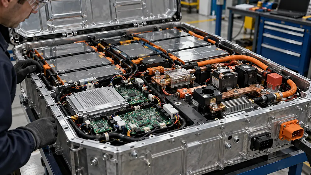
The battery management system, or BMS, is the control and protection system of the battery pack.
A BMS monitors battery conditions and helps control charging, discharging, balancing, protection, and system communication. Modern BMS designs may also estimate SOC, SOH, available power, temperature limits, and remaining battery capability. Research on BMS technology consistently identifies SOC and battery-state estimation as core functions for safe and efficient lithium-ion battery operation.
For an OEM project, the BMS specification may include:
| BMS Requirement | Example |
| Continuous discharge current | 200A |
| Peak discharge current | 400A for 10 seconds |
| Charge current | 100A |
| Main contactor control | Required |
| Pre-charge control | Required |
| SOC output | Required |
| SOH output | Optional or required |
| CAN communication | Required |
| Insulation monitoring | Required for selected HV systems |
| Temperature sensors | Multiple pack locations |
| Remote wake-up | Application dependent |
| Data logging | Optional |
| Cloud/4G monitoring | Optional |
–
For vehicles and machines that enter low-power or sleep modes, BMS wake-up signals ⇱ should also be defined so the battery, charger, VCU, or machine controller can activate the system correctly.
For higher-voltage battery systems, protection architecture may also include HV interlock, insulation monitoring, service disconnects, main positive and negative contactors, pre-charge circuits, fuses, and emergency shutdown logic.
Pre-charge deserves special attention.
When a battery is connected to an inverter or motor controller containing large DC-link capacitors, directly closing the main contactor can create a very high inrush current. A pre-charge circuit limits that initial current while the downstream capacitance charges before the main power path is closed.
This is an integration issue between the battery and the equipment, not something that should be decided independently by either side.
9. “CAN Bus” Is Not a Complete Communication Specification
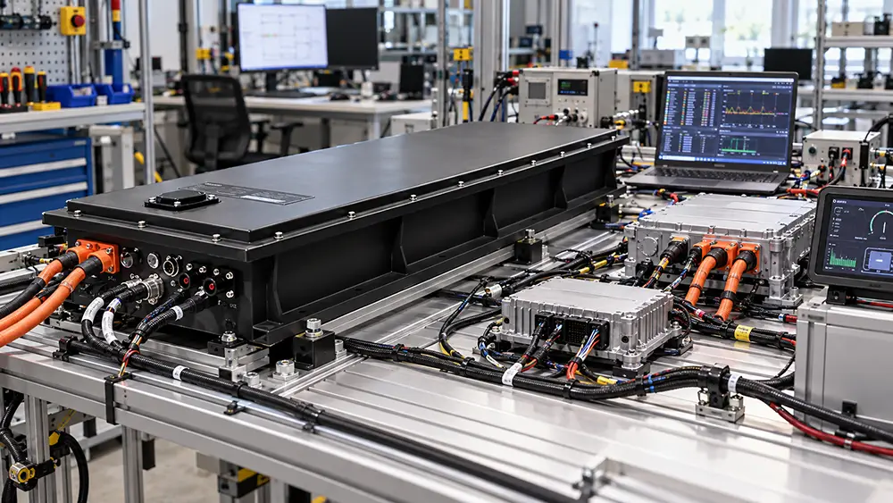
A request that says “Battery must support CAN” is still incomplete.
CAN defines the communication network, but it does not automatically define what data the battery sends, which CAN IDs are used, how the messages are formatted, or how another controller interprets them.
CAN in Automation ⇱ describes Classical CAN as an internationally standardized data-link technology under ISO 11898-1, with features such as multi-node communication, broadcasting, error detection, retransmission, and fault confinement.
Application protocols sit on top of that communication layer.
SAE J1939 ⇱, for example, is widely used in commercial vehicles, construction equipment, agricultural equipment, and related applications. SAE describes J1939 as an architecture that allows electronic control units to communicate using CAN-based data links and 29-bit identifiers.
Therefore, an OEM communication requirement should ideally identify the physical interface, baud rate, protocol, CAN IDs or PGNs, message timing, scaling, alarms, required battery data, and whether a DBC or protocol document is available.
The most important rule is simple:
CAN hardware compatibility does not guarantee protocol compatibility.
Two devices can both have CAN ports and still be unable to understand each other.
This issue appears frequently in marine propulsion, EV controllers, chargers, displays, energy gateways, and industrial vehicles.
Whenever possible, provide the battery supplier with the communication protocol before prototype hardware is finalized.
10. Charging, Temperature and Thermal Management Must Be Defined Together
A battery cannot be specified correctly without specifying how it will be charged.
The charging requirement should include charger input power source, maximum charge current, maximum charging voltage, onboard charging system ⇱ or external charger, required charging time, communication method, regenerative charging, and charging temperature.
Fast charging creates a trade-off.
Higher charge current can reduce downtime, but it can also increase heat and accelerate degradation if the cell, temperature, and charging profile are not designed for it.
A major academic review of lithium-ion fast charging ⇱ notes that high charging currents can increase degradation and that low-temperature charging creates additional challenges, including greater lithium-plating risk.
This leads to an important OEM design rule:
Charge current should be specified together with SOC range and temperature range.
For example, asking for “1C charging” is incomplete if the expected charging temperature includes -20°C.
Cold-weather operation may require charge-current derating or a battery heater before charging begins. Temperature also changes available energy, so battery capacity and temperature ⇱ should be considered together when sizing a pack for cold or hot environments.
High temperatures create the opposite problem. They may increase chemical reaction rates and accelerate aging. NREL battery lifetime research treats temperature, state-of-charge history, charge/discharge rate, and cycling pattern as important variables in lifetime prediction.
Thermal management therefore depends on the actual heat load.
A modest-current LFP pack operating intermittently may need only passive thermal management. A high-power EV pack or fast-charge system may require forced-air or liquid cooling.
Research reviews of EV battery thermal management ⇱ repeatedly show that thermal management influences battery performance, safety, temperature uniformity, and life.
Do not specify liquid cooling simply because it sounds more advanced.
Use it when the thermal analysis shows that the application needs it.
11. Certification and Testing Depend on the Application and Market
One of the most common purchasing mistakes is treating all battery standards as interchangeable.
They are not.
UN 38.3, for example, is related to lithium battery transport testing under the UN Manual of Tests and Criteria ⇱. It should not be presented as proof that a battery is certified for every vehicle, machine, or end-use application. The UNECE continues to maintain and update Section 38.3 within the Manual of Tests and Criteria.
IEC 62619 ⇱ covers safety requirements and tests for secondary lithium cells and batteries used in industrial applications. IEC specifically lists examples including forklifts, golf carts, AGVs, railway vehicles, and marine vehicles, while excluding road vehicles when more specific standards apply.
For road EV applications, standards such as ISO 6469 may become relevant depending on the vehicle and market. ISO 6469-1 ⇱ addresses safety requirements for rechargeable energy storage systems in electrically propelled road vehicles.
UL 2580 ⇱ addresses battery systems for use in electric vehicles and evaluates their ability to withstand specified electrical, mechanical, environmental, and abuse conditions.
The correct compliance plan therefore starts with three questions:
What is the final application?
Where will the product be sold?
Which regulations, certification schemes, customer standards, and shipping requirements apply to that exact product?
Cell certification does not automatically certify the complete battery pack.
Likewise, testing one battery configuration does not automatically mean every future voltage, capacity, enclosure, BMS, or cell configuration is covered.
For OEM programs, certification requirements should be discussed before design freeze because they can influence cell selection, enclosure construction, fuse design, spacing, wiring, thermal protection, labeling, and test samples.
12. Prototype Validation Is Where the Specification Becomes Real
A drawing can confirm dimensions. It cannot prove that the battery works correctly in the machine.
Before reaching this stage, the custom lithium battery pack engineering process ⇱ normally moves through cell selection, electrical design, BMS integration, thermal design, enclosure development, and prototype production.
Prototype validation should test the battery as part of the complete system.
A practical prototype program checks mechanical fit, connector access, startup sequence, pre-charge, continuous current, peak load, charging, CAN communication, SOC reporting, temperature behavior, fault handling, shutdown logic, and real runtime.
This is especially important when the battery communicates with a third-party motor controller, charger, VCU, marine display, inverter, or gateway.
One test can also reveal problems that were invisible in the original RFQ.
For example, a machine may have a short 400A load that nobody mentioned because the motor was only described as “15kW.” A charger may create a communication timeout. A cable bend radius may make the battery impossible to install even though the enclosure itself fits.
A successful prototype is therefore not just a battery sample.
It is a system-integration test.
After prototype approval, the project should move toward design freeze.
Important production-controlled items include the cell manufacturer and model, BMS hardware, firmware version, contactors, fuse, busbar design, enclosure drawing, connector model, wiring harness, communication protocol, labeling, and end-of-line test requirements.
Any critical component change should follow a controlled engineering-change process.
That matters because OEM customers are not buying one battery. They are buying repeatability.
13. A Practical Custom Lithium Battery RFQ Checklist
A useful RFQ gives the battery manufacturer enough information to evaluate feasibility without forcing the OEM to design the battery itself.
The following format works well for most projects:
| RFQ Item | Information to Provide |
| Application | What machine, vehicle, vessel or equipment is this? |
| Motor/load | Rated power and peak power |
| Nominal voltage | Required system voltage |
| Voltage limits | Controller/inverter operating range |
| Energy/runtime | Required kWh or working hours |
| Continuous current | Normal maximum sustained current |
| Peak current | Current plus duration |
| Charging | Charger voltage, power and required charge time |
| Regeneration | Yes/no and maximum regenerative current |
| Battery space | Maximum L × W × H |
| Weight | Maximum preferred battery weight |
| Installation | Fixed, removable, mounting direction |
| Environment | Indoor/outdoor/marine/dust/water/vibration |
| Temperature | Minimum and maximum charge/discharge temperature |
| Communication | CAN/J1939/RS485/custom protocol |
| Interfaces | Connectors, cables, service disconnect |
| Protection | IP target and other environmental requirements |
| Target market | Countries where equipment will be sold |
| Compliance | Required standards or customer tests |
| Prototype quantity | Initial development quantity |
| Annual quantity | Expected mass-production volume |
–
Notice what is not required at the beginning: an exact cell model.
The battery engineering team should normally recommend the cell after reviewing the complete requirement.
Who should decide what?
| Decision | OEM | Battery Engineering Team |
| Equipment application | Define | Review |
| Required runtime | Define | Verify |
| Power/load profile | Provide | Analyze |
| Battery space | Define | Optimize design |
| Chemistry | Give priorities | Recommend |
| Cell model | Review | Select |
| Series-parallel configuration | — | Design |
| BMS architecture | Define interfaces | Design |
| Thermal management | Provide environment | Design |
| Enclosure | Define installation limits | Design |
| Compliance plan | Define market | Joint review |
–
This division saves time because it lets each side provide the information it knows best.
Send Us Your OEM Battery RFQ
If you already know your voltage, load, runtime, available battery space, charging method, communication requirement, and target quantity, you have enough information to start.
Even if several details are still unknown, we can review the application first and identify what needs to be confirmed before the battery design begins.
14. Three Real-World Examples of How Requirements Change the Pack
Specifications become easier to understand when they are connected to real equipment.
Example 1: Industrial Cable-Pulling Equipment
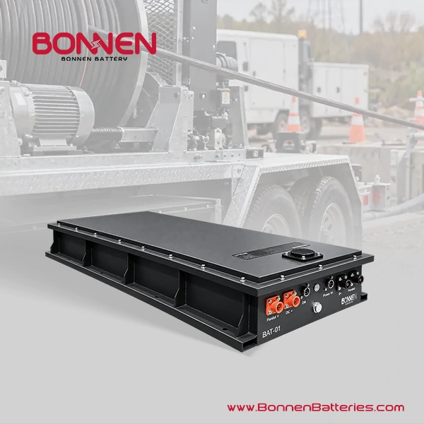
In one 96V lithium battery system for an industrial cable-pulling machine ⇱, the application combined a roughly 96V-class power system with a 10kW motor and very limited installation height. Installation height and weight distribution were critical because the battery had to fit inside a low-profile mobile machine.
A large single battery looked attractive at first because it simplified wiring.
However, mechanical balance and service handling made two smaller packs a better solution.
That changed the BMS architecture, parallel control strategy, display logic, cabling, and communication requirements.
The lesson is simple:
Mechanical constraints can change the electrical architecture.
Example 2: High-Power Electric Boat
A marine propulsion project can look simple when described only by voltage and kWh.
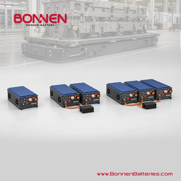
But high-power propulsion may require several hundred amps continuously. If several batteries are connected in parallel, the engineering questions expand to include current sharing, synchronized contactors, pre-charge, master-slave BMS control, insulation monitoring, emergency shutdown, and communication with onboard electronics.
The lesson:
Parallel batteries should be designed as one electrical system, not treated as independent boxes connected to the same bus.
Example 3: AGV or AMR
When specifying AMR battery systems ⇱, maximum runtime is not always the only priority.
A warehouse robot may operate many hours per day and charge during short breaks.
In that case, cycle life, charge acceptance, BMS communication, charger integration, uptime, thermal conditions, and predictable SOC may matter more than achieving the highest possible Wh/kg.
The lesson:
The best battery is the one optimized for the equipment’s business model and duty cycle, not the one with the highest specification on paper.
15. Common Specification Mistakes That Delay OEM Projects
Most custom battery delays do not begin with battery chemistry.
They begin with missing system information.
One common mistake is specifying only voltage and Ah. Another is quoting motor power without continuous and peak current. Others include choosing a cell before defining battery space, requesting CAN without supplying a protocol, requesting fast charging without defining temperature, or asking for a certification before confirming the final application and destination market.
Another mistake is designing too close to the limits.
If the equipment requires 200A continuously, selecting a battery whose absolute maximum continuous rating is exactly 200A leaves little margin for temperature, aging, manufacturing variation, auxiliary loads, or changing operating conditions.
The same principle applies to enclosure space.
A CAD cavity of 800 × 500 × 300 mm does not necessarily mean an 800 × 500 × 300 mm battery will fit. Space is needed for cables, connector mating, installation tolerance, cooling, mounting hardware, lifting, and service.
Good battery specifications therefore describe operating margins as well as nominal requirements.
16. FAQ
How much information do I need before asking for a custom battery quote?
You do not need a finished battery design. In most cases, start with the application, voltage, motor or load power, continuous and peak current if known, required runtime, maximum battery space, charging method, operating temperature, communication requirement, target market, prototype quantity, and expected annual volume.
Can you design a battery if I only know the motor power and voltage?
Usually we can begin the discussion, but motor power and voltage are not enough for final design. We will also need to understand continuous load, peak load, peak duration, runtime, controller voltage range, battery space, charging method, environment, and how the machine operates during a normal working cycle.
How do I calculate the battery capacity I need?
Start with the average electrical power used by the equipment and multiply it by the required operating time. A machine averaging 5kW for three hours needs about 15kWh of delivered energy. The nominal battery should normally be larger because the full theoretical capacity may not be used and additional margin may be needed for losses, temperature and aging.
Should I specify Ah or kWh?
Ideally, specify both. Ah describes electrical charge capacity, while kWh describes energy. kWh is usually more useful for comparing batteries of different voltages because a 100Ah 48V battery contains much less energy than a 100Ah 96V battery.
How do I know what voltage my custom battery should use?
Start with the operating voltage range of the inverter, motor controller, charger, DC/DC converter and other connected equipment. The battery’s maximum charged voltage and minimum operating voltage must stay inside the acceptable range of the complete system.
How do I determine the peak battery current?
The best source is measured controller or machine data. If that is unavailable, motor or inverter peak power can provide an early estimate using current = power ÷ voltage, but efficiency, voltage sag, auxiliary loads and transient behavior must still be considered.
Is “400A peak current” enough information for the battery supplier?
No. Always include the peak duration and, if possible, how often the peak occurs. A battery that must deliver 400A for two seconds has a different thermal requirement from one that must deliver 400A for 60 seconds.
Should I choose LFP or NMC for my OEM battery?
Choose based on the project rather than chemistry preference. LFP is often attractive for long cycle life, frequent use and thermal stability, while NMC can be useful when weight and space are highly restricted. The correct choice depends on energy, power, size, weight, temperature, lifetime and cost targets.
Can I tell the battery manufacturer which cell I want to use?
Yes, but it is often better to describe why you prefer that cell. If your real goal is low weight, long life, fast charging or high current, the engineering team may know another cell that meets the requirement better or has better long-term supply availability.
What does the BMS need to communicate with my machine?
That depends on the equipment. Typical data includes SOC, voltage, current, cell temperature, allowable charge current, allowable discharge current, alarms and fault status. The exact CAN IDs, message format, update rate and protocol must be agreed between the battery and equipment teams.
If both devices have CAN, will they communicate?
Not necessarily. CAN provides the communication network, but the devices still need compatible higher-level messages and data definitions. Two products with CAN ports can use completely different CAN IDs, message structures, baud rates or application protocols.
Do I need pre-charge in a custom battery system?
Many systems with motor controllers or inverters use pre-charge because their DC-link capacitors can draw a large inrush current when first connected. Whether pre-charge is needed and how it should be controlled must be confirmed with the inverter or controller design.
Can lithium batteries charge below 0°C?
Some cells and battery systems allow limited low-temperature charging, while others require charging to stop or the battery to be heated first. Fast charging at low temperature can increase degradation risk, including lithium plating, so the charging strategy must follow the selected cell’s limits rather than a general lithium-battery rule.
Is IP67 enough for a marine battery?
Not by itself. IP67 addresses specific dust and water ingress test conditions, but a marine battery may also need appropriate protection against salt, corrosion, condensation, vibration, shock, UV exposure and long-term sealing degradation. The complete environmental requirement should be defined from the vessel and installation location.
Does UN 38.3 mean my battery is certified for my vehicle or machine?
No. UN 38.3 is associated with lithium battery transport testing. Product safety and end-use compliance depend on the battery application, destination market and applicable standards. A transport test should not be presented as universal equipment certification.
Does using certified cells mean the complete battery pack is certified?
Not automatically. The final pack includes the cells, BMS, wiring, contactors, fuse, enclosure, connectors, thermal design and mechanical structure. Depending on the required standard, certification or testing may apply to the final battery or representative battery configuration rather than only to the cells.
Should I request liquid cooling for a high-power battery?
Only when the heat load and operating conditions justify it. High current, fast charging, compact packaging, high ambient temperatures and continuous operation can increase the need for active cooling, but lower-power systems may work well with simpler thermal solutions.
How important is the prototype stage if the battery has already passed factory testing?
Factory testing and equipment validation serve different purposes. Factory testing checks the battery itself, while prototype installation confirms mechanical fit, electrical integration, charging, communication, startup, load behavior, thermal performance and fault handling inside the real machine.
What should I provide if my battery space has an unusual shape?
A 3D STEP model is ideal. At minimum, provide a detailed drawing showing maximum dimensions, mounting points, forbidden areas, cable exits, connector access, surrounding components and installation direction. Photos are useful, but dimensional CAD data is much better for custom enclosure development.
How early should I discuss certification with the battery supplier?
Discuss it before the design is frozen. Certification requirements can influence cell selection, enclosure design, insulation, spacing, protection devices, wiring, labels and the number of samples needed for testing. Late certification changes can create expensive redesign work.
What is the single most useful document I can send for a custom battery project?
A one-page battery requirement sheet that combines the application, voltage range, load profile, runtime, available space, charging method, operating environment, communication interface and expected quantity is often more useful than a long document containing only battery component preferences.
17. Final Takeaway: Specify the Application First
The most important rule in custom lithium battery development is simple:
Do not start by specifying the battery. Start by specifying the job the battery must perform.
A strong OEM battery specification defines five things clearly: the electrical load, required energy, mechanical limits, operating environment, and system interfaces.
From those requirements, the battery engineering team can select the chemistry, cells, series-parallel configuration, BMS, contactors, fuse, thermal system, enclosure, connectors, charging strategy, and communication architecture.
The process can be summarized in three steps:
First, define the equipment and duty cycle.
Second, translate that duty cycle into voltage, energy, current, mechanical, environmental, and communication requirements.
Third, validate the resulting battery inside the real equipment before freezing the design for mass production.
Voltage and Ah may start the conversation.
A complete system specification is what makes an OEM battery project successful.
Contact Bonnen Battery↓ now and let us help you power your adventures with the best lithium battery technologies.
© [Bonnen Battery] and [www.bonnenbatteries.com]. Unauthorized use and/or duplication of this material without express and written permission from this site’s author and/or owner is strictly prohibited. Excerpts and links may be used, provided that full and clear credit is given to [Bonnen Battery] and [www.bonnenbatteries.com] with appropriate and specific direction to the original content.