Last Updated on 20/10/2026 by Bonnen Battery
Electric Boat Battery System Architecture: A Complete Guide
An electric boat battery system is more than a lithium battery connected to an electric motor. A complete system includes the battery pack, Battery Management System (BMS), power distribution, motor controller, charging equipment, and communication network. These components must work together to deliver propulsion power, manage charging, monitor battery conditions, and protect the system when something goes wrong.
For boat builders and OEM engineers, choosing the right battery voltage and capacity is only the beginning. The real challenge is making sure every component works together. A perfectly good battery can still become a major headache when the motor controller, charger, and BMS do not communicate properly.
This guide explains how electric boat battery systems work, their main components, common 48V, 72V, 96V, and higher-voltage architectures, parallel battery configurations, communication requirements, and safety considerations. We will also walk through practical marine battery system design examples.
1. What Is an Electric Boat Battery System Architecture?
An electric boat battery system architecture describes how the battery, electrical equipment, control devices, and communication systems are connected and how they operate together.
In simple terms, it is the blueprint for the boat’s electrical propulsion system.
It answers several important questions:
- Where does the propulsion power come from?
- How does electricity reach the motor?
- What controls charging and discharging?
- How are battery faults detected and managed?
- How does the operator monitor battery status?
- What happens when part of the system stops working?
A battery pack alone cannot answer all these questions.
For example, a 72V-class lithium battery may have sufficient energy to operate an electric propulsion motor. But the complete system still needs suitable power distribution, electrical protection, charging equipment, and control logic.
The battery must also operate within the motor controller’s voltage range and supply the required current under actual operating conditions.
Battery Pack vs. Complete Battery System
The difference becomes clearer when we compare the two.
| Battery Pack | Complete Battery System |
|---|---|
| Lithium battery cells | One or multiple battery packs |
| Battery enclosure | System-level electrical protection |
| Battery Management System | Power Distribution Unit (PDU) |
| Internal electrical connections | Main contactors and pre-charge system |
| Pack voltage and temperature monitoring | Motor controller integration |
| Pack-level protection | Charging system integration |
| Optional battery communication interface | Vessel monitoring and system control |
Some of these functions may be built into the battery enclosure. Others may be installed in a separate electrical cabinet.
There is no single architecture suitable for every boat.
A small electric tender may use a relatively simple 48V battery system. A medium-sized electric leisure boat may use a 72V or 96V-class system. A larger commercial electric vessel may require multiple battery packs, more advanced control functions, and higher-voltage electrical equipment.
These are examples rather than fixed categories. The correct voltage depends on the propulsion equipment and actual operating requirements.
2. How Does an Electric Boat Battery System Work?
The basic operating principle is straightforward.
The battery stores electrical energy. A motor controller converts and regulates that energy to operate the electric propulsion motor. Meanwhile, the BMS monitors battery conditions, and the protection system manages electrical faults and safe connection or disconnection.
However, the actual system contains several connected functions.
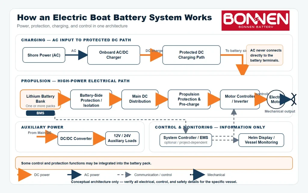
The Propulsion Power Path
The main propulsion power path typically follows this sequence:
Battery Bank → Electrical Protection and Distribution → Motor Controller → Electric Motor → Propeller
In most modern electric boat propulsion systems, the lithium battery supplies DC power.
The motor controller, often called an inverter in AC motor systems, controls the electrical power delivered to the motor according to the operator’s throttle command and the available system limits.
The motor converts electrical energy into mechanical power to drive the propeller.
The motor controller must be compatible with the battery’s complete operating voltage range, not just its nominal voltage.
This is equally important for 48V, 72V, 96V, and higher-voltage battery systems.
The Charging Power Path
Charging uses a different operating path:
Shore Power → Onboard Charger → Protected DC Charging Path → Battery Bank
The onboard charger converts incoming AC power into the regulated DC voltage and current required by the battery.
The BMS monitors battery conditions and may communicate charging limits or permissions to the charger.
Some boats also include solar panels, generators, or other energy sources. These require suitable charging or power conversion equipment.
They should not be connected directly to a lithium battery without the necessary voltage regulation, control, and protection.
The Communication Path
Electrical power and communication are two different things.
High-current cables carry energy. Communication cables carry information.
A typical communication path may look like this:
Battery BMS → System Controller → Motor Controller / Charger / Monitoring Display
The BMS can provide information such as:
- Battery voltage and current
- State of charge (SOC)
- Battery temperature
- Available charging current
- Available discharge current
- Warning and fault status
The system controller uses the relevant information to coordinate equipment operation.
Not every boat requires a separate system controller. Some propulsion systems communicate directly with the battery BMS.
The correct arrangement depends on which device is responsible for each control and safety function.
3. Main Components of an Electric Boat Battery System
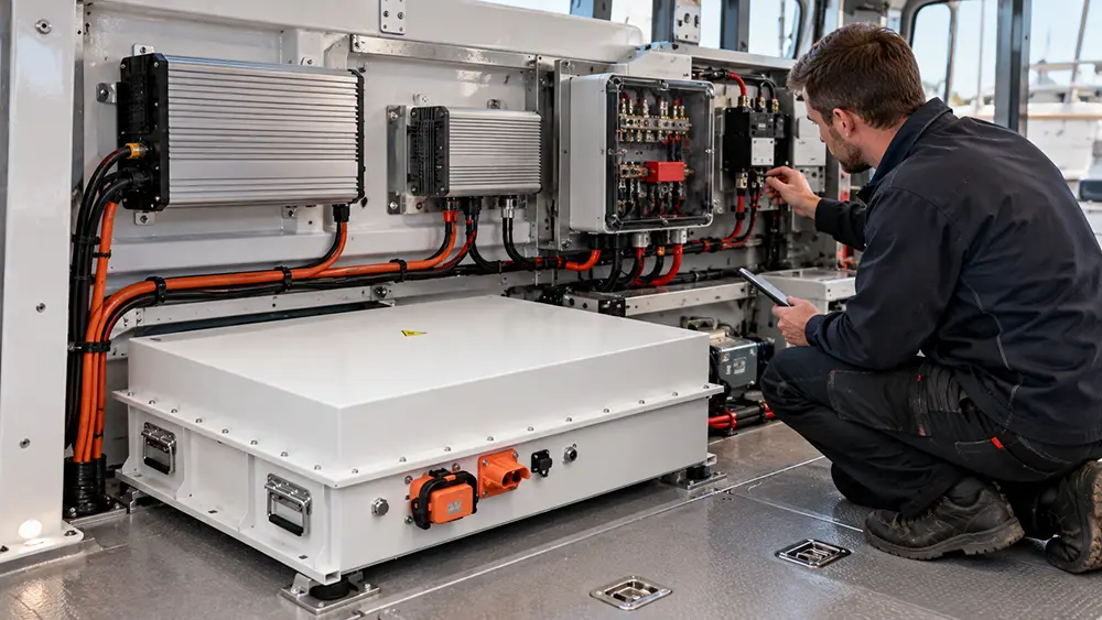
A complete electric boat battery system contains several important components. Each has a different responsibility.
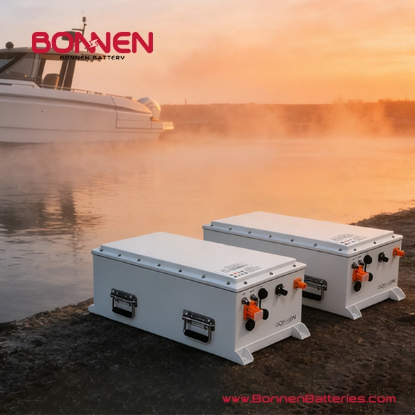
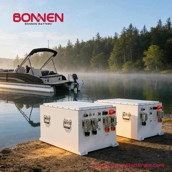
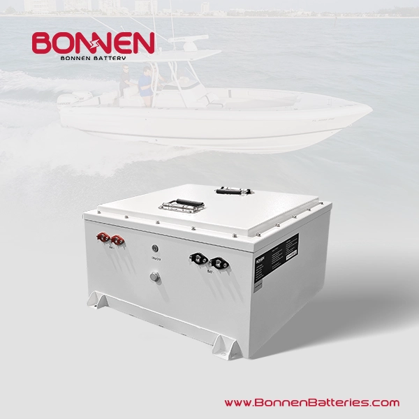
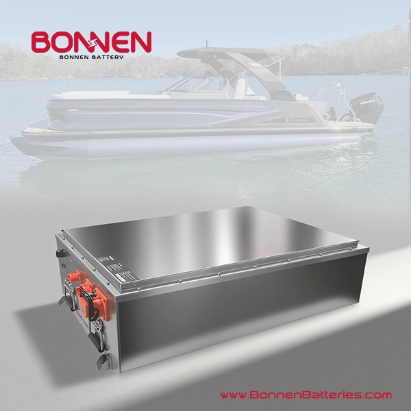
3.1 Lithium Battery Pack
The battery pack stores the energy required for propulsion.
Marine lithium batteries commonly use lithium iron phosphate (LiFePO4 or LFP) and, for some applications, nickel manganese cobalt (NMC) chemistry.
LFP is often selected for electric boats because of its thermal stability, cycle-life characteristics, and suitability for demanding applications.
NMC can offer advantages where energy density and weight are especially important. However, the final choice must consider the actual cell design, protection system, thermal management, and operating conditions.
Battery capacity is usually expressed in ampere-hours (Ah) or kilowatt-hours (kWh).
For example, a 72V-class battery using 24 LFP cells in series has a nominal voltage of 76.8V.
A 76.8V 200Ah battery provides:
76.8V × 200Ah ÷ 1,000 = 15.36 kWh
By comparison, a 102.4V 200Ah battery provides:
102.4V × 200Ah ÷ 1,000 = 20.48 kWh
These are nominal energy calculations.
The actual usable energy depends on the allowed SOC range, temperature, discharge rate, aging, and other operating conditions.
3.2 Battery Management System (BMS)
The BMS monitors and manages battery operation.
Depending on the design, its functions may include:
- Cell voltage monitoring
- Battery current monitoring
- Temperature monitoring
- Cell balancing
- SOC estimation
- Charge and discharge limits
- Fault detection
- Contactor control
- Communication with external equipment
A good BMS does more than disconnect the battery when something goes wrong.
In a properly integrated system, it can help external equipment respond before a protective shutdown becomes necessary.
For example, if the battery becomes too hot, the BMS may reduce the permitted discharge current. A compatible propulsion controller can then reduce available motor power.
This is usually better than allowing the battery to disconnect suddenly while the boat is operating.
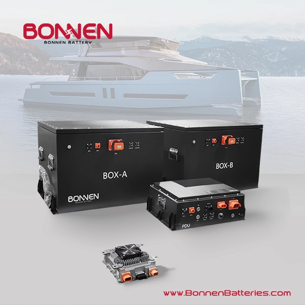
3.3 Power Distribution Unit (PDU)
The PDU organizes electrical distribution and protection between the battery bank and connected equipment.
Depending on the architecture, it may include:
- DC busbars
- Main contactors
- Fuses
- Current sensors
- Voltage measurement
- Pre-charge components
- Service disconnects
- Insulation monitoring equipment
Some compact 48V or 72V systems integrate several of these functions inside the battery pack.
Larger 72V, 96V, or high-voltage systems may use a separate PDU.
The actual arrangement depends on the battery and propulsion system design, not voltage alone.
Important: A BMS and PDU are not the same thing. The BMS supervises battery operation, while the PDU contains equipment that manages power connections and distribution. Their responsibilities may overlap, but one does not automatically replace the other.
3.4 Main Contactors
Main contactors connect or disconnect the battery from the power system.
They may be operated according to BMS commands, system controller commands, or a coordinated safety sequence.
The contactors must be correctly rated for the system’s DC voltage, current, and switching conditions.
Their ability to carry continuous current does not necessarily mean they can safely interrupt every possible fault current.
Appropriate DC-rated overcurrent protection is still required.
3.5 Pre-charge System
Many motor controllers contain DC-link capacitors.
When a discharged capacitor is connected directly to a battery, a very high inrush current can occur.
This may damage contactors or other electrical components.
A pre-charge circuit allows the controller’s DC-link voltage to rise in a controlled way before the main propulsion power path is fully connected.
The system may use a pre-charge resistor and a controlled switching sequence.
The correct resistor value, power rating, timing, and voltage verification must be calculated for the actual equipment.
A pre-charge circuit is not just an optional accessory when the connected equipment requires it.
3.6 Motor Controller and Electric Motor
The motor controller manages the power supplied to the propulsion motor.
It must match the battery voltage range and support the required continuous and peak operating power.
It must also respond correctly to battery warnings and operating limits when such coordination is part of the architecture.
For example, a motor controller designed for a 72V propulsion platform must be checked against the actual minimum and maximum voltages of the selected battery pack.
The motor then converts electrical energy into propulsion.
Motor power and battery power are related, but they are not identical. Electrical and mechanical losses must be considered during system sizing.
3.7 Onboard Charger and DC/DC Converter
The onboard charger supplies regulated charging power from an AC source.
A DC/DC converter changes the propulsion battery voltage into another DC voltage, commonly 12V or 24V, for appropriate onboard equipment.
For example, a 72V-class propulsion battery may support a 12V auxiliary electrical system through a suitable DC/DC converter.
Critical equipment may require an independent auxiliary battery or other backup arrangements.
The propulsion battery should not become a single point of failure for essential boat safety equipment without a properly assessed system design.
4. Common Electric Boat Battery Architectures: 48V, 72V, 96V, and High Voltage
One of the first decisions in electric boat system design is the battery voltage.
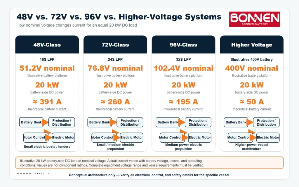
Common options include 48V-class, 72V-class, 96V-class, and higher-voltage systems.
The right voltage depends on motor requirements, current, installation space, safety considerations, and the overall electrical architecture.
4.1 48V Electric Boat Battery Architecture
A 48V-class system is often suitable for smaller electric boats, tenders, sailboats, and lower-power propulsion applications.
A common LFP configuration is 16 cells in series, giving a nominal battery voltage of 51.2V.
Advantages may include a relatively simple overall architecture and a wide selection of compatible equipment.
However, low voltage does not mean low current.
For example, a 20 kW electrical load at a nominal 51.2V requires approximately:
20,000W ÷ 51.2V = 391A
This calculation excludes additional current caused by voltage reduction or conversion losses.
Large currents increase the demands on cables, connectors, busbars, contactors, and protection equipment.
4.2 72V Electric Boat Battery Architecture
A 72V-class system ⇱ provides another option between the common 48V and 96V propulsion platforms.
It can be considered for electric boats using motors and controllers designed for this voltage range.
For LFP batteries, a 24-series configuration has a nominal voltage of 76.8V.
Some battery systems using other lithium chemistries may have a nominal voltage closer to 72V. Therefore, “72V battery” should be treated as a platform description until the actual cell chemistry and series configuration are confirmed.
At a nominal 76.8V, a 20 kW electrical load requires approximately:
20,000W ÷ 76.8V = 260A
That is about one-third less current than the equivalent 51.2V example.
This can make a 72V-class system attractive when the selected propulsion equipment supports it and the designer wants to avoid the very high current associated with lower-voltage configurations.
However, the complete system still needs appropriately rated cables, contactors, fuses, pre-charge equipment, and charging components.
When Should You Consider a 72V Marine Battery?
A 72V-class architecture may be worth evaluating when:
- The propulsion motor controller is designed for a 72V-class battery.
- A 48V-class system would require relatively high current.
- The boat needs a moderate amount of propulsion power and battery energy.
- Battery size and weight distribution favor one or several compact packs.
- The charging equipment supports the battery’s full operating voltage range.
- The required BMS communication and protection functions can be integrated.
For OEM boat builders, 72V can be a useful design option. It should not be selected simply because it sits between 48V and 96V.
The motor controller’s approved input voltage range should come first.
4.3 96V Electric Boat Battery Architecture
A 96V-class system ⇱ is commonly considered for electric propulsion applications where lower current is desirable.
For LFP batteries, a 32-series configuration has a nominal voltage of 102.4V.
However, not every battery marketed as a 96V system has a 102.4V nominal voltage. Cell chemistry, series count, and manufacturer definitions matter.
At a nominal 102.4V, the same 20 kW electrical load requires approximately:
20,000W ÷ 102.4V = 195A
That is approximately half the current required at 51.2V and about 25% less than the 76.8V example.
Lower current can reduce some cable and distribution requirements, but higher voltage also creates additional electrical safety and component selection challenges.
The motor controller, charger, BMS, and electrical protection must all support the selected voltage platform.
4.4 High-Voltage Electric Boat Battery Architecture
Larger electric boats, commercial vessels, and high-power propulsion systems may use battery platforms such as 300V, 400V, 600V, or other project-specific voltages.
Higher voltage can help deliver substantial power without extremely high current.
However, these systems generally need more demanding insulation coordination, electrical isolation, switching equipment, safety procedures, and service controls.
The regulatory meaning of “high voltage” is not the same in every standard or jurisdiction. Engineers should use the definitions and requirements applicable to the vessel.
Comparing 48V, 72V, 96V, and Higher-Voltage Systems
| Design Factor | 48V Class | 72V Class | 96V Class | Higher Voltage |
|---|---|---|---|---|
| Example nominal LFP voltage | 51.2V | 76.8V | 102.4V | Project-dependent |
| Example LFP configuration | 16S | 24S | 32S | Project-dependent |
| General application | Smaller boats | Small and medium propulsion projects | Medium-power propulsion projects | Higher-power vessels |
| Current for 20 kW DC load | About 391A | About 260A | About 195A | Depends on voltage |
| Battery arrangement | Single or parallel | Single or parallel | Single or parallel | Modular, project-dependent |
| Electrical protection | Required | Required | Required | More demanding |
| Communication | Equipment-dependent | Equipment-dependent | Equipment-dependent | Equipment-dependent |
| Design complexity | Often lower | Project-dependent | Moderate to high | Often higher |
The current values are simple nominal-voltage examples, not final design currents. The application descriptions are general examples rather than strict power classifications.
The best battery voltage is the one that matches the complete propulsion system—not simply the highest voltage available.
5. Single Battery vs. Parallel Battery Architecture
Some electric boats can meet their energy and power requirements with one battery pack.
Others need multiple packs operating together.
Single Battery Architecture
A single battery system generally has fewer external interconnections.
This can simplify installation, communication, and system testing.
However, one large battery enclosure may create challenges related to weight, available space, maintenance access, and installation.
It also offers less flexibility when batteries need to be placed in different compartments to improve weight distribution.
Parallel Battery Architecture
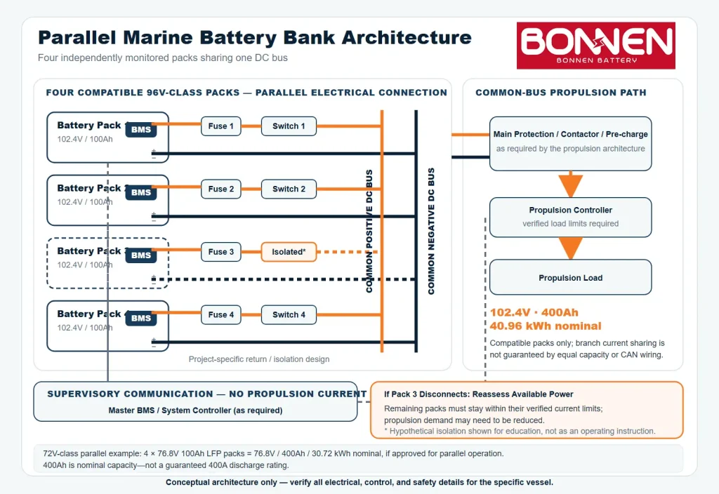
In a parallel system ⇱, compatible battery packs connect to a common DC voltage platform to increase total energy capacity and potentially available discharge power.
For example, four 76.8V 100Ah LFP battery packs provide:
76.8V × 400Ah ÷ 1,000 = 30.72 kWh
The nominal system voltage remains 76.8V.
Likewise, four 102.4V 100Ah batteries provide:
102.4V × 400Ah ÷ 1,000 = 40.96 kWh
The nominal system voltage remains 102.4V.
Both calculations assume compatible packs connected in an approved parallel configuration.
However, parallel battery design is more complicated than connecting positive terminals together and negative terminals together.
Each branch may require appropriate fusing, switching, current monitoring, and coordination.
How Does Current Sharing Work?
Current does not necessarily divide equally between parallel batteries.
Actual current sharing depends on factors such as:
- Battery voltage and SOC
- Internal resistance
- Cable and connection resistance
- Battery temperature
- BMS and contactor behavior
- Individual battery current limits
For a properly designed system, the battery packs should be compatible and the current paths should be engineered to avoid unacceptable imbalance.
Communication can help coordinate the system, but CAN messages do not physically force current to share equally.
For a deeper explanation of how cable resistance and connection layout affect current sharing, see Victron Energy’s Battery Bank Wiring Guide ⇱.
What Happens if One Battery Disconnects?
This is one of the most important design questions.
Imagine four packs supplying an electric motor.
If one pack disconnects because of a fault, the remaining three packs must carry the load or the propulsion system must reduce its demand.
If the controller keeps demanding the original power, the remaining batteries may exceed their allowed current.
The system should therefore have an agreed fault response and power-limiting strategy.
For larger battery banks, a master BMS or dedicated system controller may monitor individual packs and calculate the available system-level operating limits.
The exact arrangement depends on the selected battery hardware.
Never assume that a battery designed for standalone use can safely operate in parallel without manufacturer approval and system-level validation.
6. Battery Communication and Vessel Monitoring
Modern electric boats often need battery data to appear on a propulsion display, system controller, or multifunction marine display.
This is where communication becomes important.
BMS CAN Bus Communication
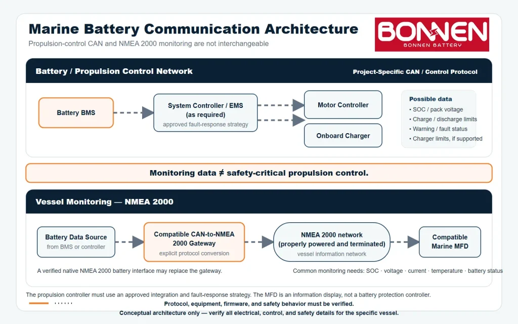
CAN bus allows electronic equipment to exchange structured information.
In an electric boat, the BMS may use CAN to communicate with the motor controller, charger, or central system controller.
Depending on the protocol, this may include battery SOC, operating limits, warnings, and control information.
But having a CAN port does not automatically mean two devices are compatible.
The devices must support suitable communication settings, message definitions, timing, and operating logic.
This applies whether the battery is 48V, 72V, 96V, or another voltage.
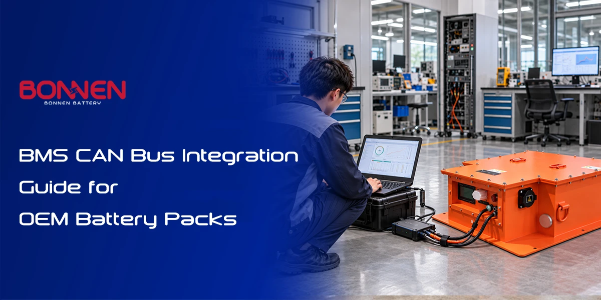
For a deeper explanation, read our BMS CAN Bus Integration Guide for OEM Battery Packs ⇱.
What Is NMEA 2000?
NMEA 2000 ⇱ is a CAN-based marine communication standard used to exchange information between compatible onboard electronic devices.
With a suitable implementation, battery information may be displayed on multifunction displays and other vessel monitoring equipment.
Common battery-related information includes voltage, current, temperature, and status.
However, a generic CAN interface is not the same as a complete NMEA 2000 interface.
A battery BMS needs a compatible NMEA 2000 implementation or an appropriate gateway that translates its data into the required messages.
A communication gateway may solve a monitoring problem, but it should not automatically be treated as a safety-critical propulsion controller.
Can Marine Batteries Communicate with Victron or Simrad?
Sometimes, but compatibility must be checked.
As explained in Victron’s Cerbo GX documentation ⇱, third-party battery integration depends on supported communication protocols and compatible equipment configurations.
The actual integration depends on the GX model, battery protocol, firmware, connected power equipment, and supported operating functions.
For Simrad and other marine multifunction displays, the battery may need to provide compatible NMEA 2000 battery data directly or through a suitable gateway.
The presence of a CAN connector alone is not enough.
Monitoring and Propulsion Control Are Different
Consider two communication functions.
Monitoring: The display shows that the battery SOC is 45%.
Control: The BMS requests a reduced discharge current because one cell is approaching a protection limit.
The first function provides information to the operator.
The second may affect how the propulsion system operates.
A complete architecture must define which device is responsible for each function and what happens when communication fails.
If a display stops receiving battery data, the propulsion system may still be able to operate safely.
If the motor controller loses critical battery control information, the required response could be very different.
These situations should be designed and tested separately.
7. Charging System Architecture for Electric Boats
Charging is an essential part of the battery architecture.
A battery system that works perfectly during discharge can still experience problems if the charger, BMS, and charging control logic are incompatible.
Shore Power Charging
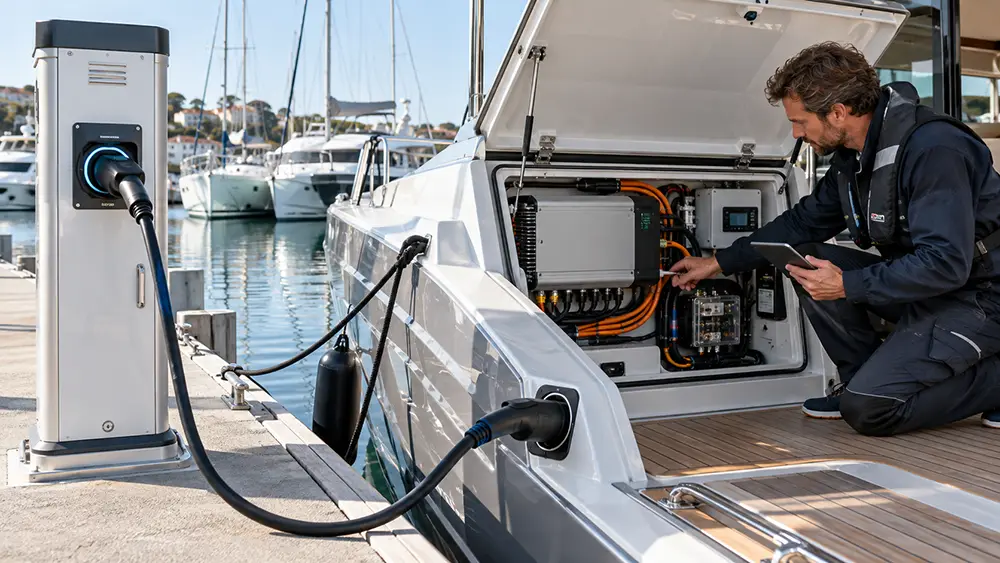
Many electric boats use an onboard AC charger connected to marina shore power.
The charger converts AC input into controlled DC charging power.
Its output voltage and current must match the battery chemistry, series configuration, and permitted charging limits.
For example, a 24S LFP battery has a nominal voltage of 76.8V, while a 32S LFP battery has a nominal voltage of 102.4V.
Both batteries require charging voltages higher than their nominal voltages.
Their charging profiles are not interchangeable.
A charger described only as a “72V charger” should never be selected without confirming its actual output range, charging profile, and battery compatibility.
BMS and Charger Communication
Some chargers operate using configured voltage and current settings, with separate enable or protection signals.
Others communicate directly with the BMS through CAN or another interface.
A suitable system may use battery information to adjust charging current based on temperature, SOC, or cell voltage conditions.
For example, charging current may need to be reduced when the battery approaches its upper voltage limit.
The charger should respond according to the agreed charging control strategy.
Solar Charging and Additional Energy Sources
Solar panels can provide useful additional energy, especially for boats operating slowly or spending long periods at anchor.
However, solar charging requires a compatible charge controller or conversion system.
The controller must support the solar array’s voltage range and the battery’s charging requirements.
The same principle applies to generators, hybrid propulsion systems, and other onboard energy sources.
Each power source needs to be integrated into the complete electrical architecture.
Charging Time Estimation
A simple estimate is:
Charging Time ≈ Energy to Replenish ÷ Effective Charging Power
For example, replacing 20 kWh of energy using an effective charging power of 3 kW would take approximately 6.7 hours.
Actual charging time may be longer because charging power can vary with battery conditions, AC supply limits, and the charging profile.
The final stage of charging may also take longer as current decreases.
8. Safety and Protection Architecture
Marine electrical systems operate in demanding environments.
Moisture, vibration, salt exposure, limited installation space, and difficult emergency access all affect electrical design.
A reliable battery architecture must consider much more than cell performance.
Overcurrent and Short-Circuit Protection
Fuses and suitable circuit protection devices help protect conductors and equipment against excessive current.
They must be selected for the actual DC voltage, prospective fault current, interruption rating, cable protection requirements, and installation conditions.
A BMS electronic protection function does not automatically replace properly rated overcurrent protection.
Contactor and Pre-charge Coordination
The system should define how the battery connects to the propulsion equipment.
For equipment requiring pre-charge, the sequence normally needs to verify that the DC-link voltage has reached an acceptable level before closing the relevant main contactor.
The system should also respond appropriately when pre-charge fails.
Repeatedly attempting to energize a system with an unresolved fault is not a safe operating strategy.
Electrical Insulation Monitoring
Insulation monitoring may be required or appropriate for some electrical propulsion architectures, especially higher-voltage isolated DC systems.
Its purpose is to detect deterioration in electrical insulation before it creates a more serious hazard.
The need for insulation monitoring, protective bonding, isolation, and other measures depends on the system design and applicable standards.
A 72V-class system should not be considered automatically safe simply because its voltage is lower than a 96V or high-voltage installation.
Thermal Management
Battery performance and safety depend on temperature.
The system should consider cell temperature, enclosure ventilation or cooling, charging restrictions, installation environment, and expected operating conditions.
A battery intended for occasional leisure use may face different thermal demands from one installed in a commercial workboat operating for many hours every day.
The cooling approach should be designed around actual heat generation and operating conditions.
Emergency Shutdown and Fault Response
An electric propulsion system should have a defined strategy for abnormal conditions.
Examples include:
| Fault Condition | System Response to Evaluate |
|---|---|
| Battery overtemperature | Reduce permitted power or initiate a controlled shutdown |
| Low battery voltage | Warn operator and limit power where appropriate |
| BMS communication loss | Apply the defined communication-loss safety strategy |
| Main contactor fault | Prevent unsafe energization or re-energization |
| Pre-charge failure | Stop the startup sequence |
| Insulation fault | Trigger the response required by the system design |
| One parallel pack disconnects | Recalculate available power and manage remaining packs |
These are engineering considerations, not universal fault-response settings. The final action must be defined according to the system’s hazards, equipment capabilities, and operating requirements.
Marine Standards and Compliance
Boat builders and system integrators should also consider relevant electrical and battery standards.
Examples include:
| Standard | Main Relevance |
|---|---|
| ISO 16315 ⇱ | Electrical systems used for electric and hybrid propulsion in small craft |
| ISO 23625 ⇱ | Lithium-ion batteries and battery systems used on small craft |
| ABYC E-11 ⇱ | AC and DC electrical systems on boats |
| ABYC E-13 ⇱ | Lithium-ion batteries |
| ABYC E-30 ⇱ | Electrical propulsion systems |
The applicable requirements depend on vessel type, size, market, installation, and any classification or regulatory obligations. The latest applicable editions should be confirmed for each project.
These standards are not interchangeable, and using a component that meets one standard does not automatically establish compliance for the complete boat.
Final installation and commissioning should be performed by qualified marine electrical professionals.
9. Example: Designing a 96V-Class Electric Boat Battery System
Let’s put the theory into practice.
Suppose a boat builder is developing a small electric leisure boat with a 20 kW propulsion motor.
The project needs approximately 40 kWh of nominal battery energy.
For this illustrative design, we will use two 102.4V 200Ah LFP battery packs connected in parallel.
The battery platform belongs to the commonly discussed 96V class, although the example packs have a nominal voltage of 102.4V.
Step 1: Define the Main Requirements
| Parameter | Example Requirement |
|---|---|
| Application | Electric leisure boat |
| Propulsion motor rating | 20 kW |
| Battery chemistry | LFP |
| Battery nominal voltage | 102.4V |
| Battery capacity per pack | 200Ah |
| Number of packs | 2 |
| Connection | Parallel |
| Nominal total energy | 40.96 kWh |
| Charging | Onboard AC charger |
| Communication | Project-specific CAN |
| Monitoring | Battery display or compatible vessel interface |
This is an educational design example, not a tested or approved boat configuration.
Step 2: Calculate Battery Energy
Each battery provides:
102.4V × 200Ah ÷ 1,000 = 20.48 kWh
Two batteries provide:
20.48 kWh × 2 = 40.96 kWh
Because the batteries are connected in parallel, the nominal voltage remains 102.4V.
The combined nominal capacity becomes 400Ah.
Step 3: Estimate Propulsion Current
Assume the complete propulsion system draws 20 kW of DC electrical power from the battery at nominal voltage.
The battery current is approximately:
20,000W ÷ 102.4V = 195A
With two packs sharing current evenly, the average current would be about 97.7A per pack.
However, current sharing will not always be perfectly equal.
The system must also account for lower battery voltage, transient motor demand, unequal current distribution, and applicable design margins.
If 20 kW refers to mechanical shaft output rather than battery-side electrical input, the electrical demand will be higher because the motor and controller are not 100% efficient.
The battery’s continuous and peak discharge capability must therefore be verified against the actual motor-controller specification.
Step 4: Select the Battery Distribution Architecture
The two batteries can connect to a common DC distribution system through appropriately designed individual protection and switching arrangements.
The architecture should address:
- Branch-level electrical protection
- Positive and negative DC busbar sizing
- Contactor control
- Pre-charge for the propulsion controller
- Individual battery current monitoring
- BMS communication
- Fault isolation and safe shutdown
Exact component ratings and connection details must be determined during electrical design.
Step 5: Define the Communication Strategy
Each battery BMS may report its operating data to a master controller.
The master controller can then calculate or communicate system-level limits when the hardware and software support that arrangement.
The propulsion controller needs to respond correctly to those limits.
For example, suppose each battery is approved to supply 150A continuous current under the relevant conditions.
Together, the two packs may support the planned nominal load, subject to verified current sharing and system limits.
But if one pack disconnects, the remaining battery cannot simply be expected to supply the original 195A load.
The system must reduce demand or follow another validated safe operating strategy.
This is why parallel architecture needs more than additional battery capacity.
Step 6: Estimate Operating Time
Suppose the system uses 80% of its nominal energy for planning purposes.
The estimated usable energy is:
40.96 kWh × 80% = 32.77 kWh
At a constant 20 kW battery-side electrical draw:
32.77 kWh ÷ 20 kW = 1.64 hours
That is approximately 1 hour and 38 minutes.
This is only a simplified energy estimate.
Real operating time depends on boat speed, hull design, water conditions, propeller efficiency, auxiliary loads, battery temperature, and the actual propulsion power profile.
A boat does not consume full rated motor power every minute.
Step 7: What If the Boat Uses a 72V Battery Instead?
Now consider a different electric boat project using a motor controller designed for a 72V-class battery.
Suppose the boat builder selects two 76.8V 200Ah LFP batteries in parallel.
Each battery provides:
76.8V × 200Ah ÷ 1,000 = 15.36 kWh
The combined battery bank provides:
15.36 kWh × 2 = 30.72 kWh
At a nominal voltage of 76.8V, a 20 kW battery-side electrical load would require approximately:
20,000W ÷ 76.8V = 260A
With ideal equal current sharing, each pack would supply approximately 130A.
The actual battery current limits and current-sharing behavior would still need to be verified.
This example shows an important difference between 72V and 96V-class systems.
At the same ampere-hour capacity, the higher-voltage configuration stores more nominal energy and requires less current for the same electrical power.
However, the two configurations are not interchangeable.
The choice depends on the motor controller’s requirements, expected energy consumption, battery installation space, electrical protection, and system compatibility.
Step 8: Verify Installation and Safety
Before approving either design, the boat builder should confirm the battery compartment dimensions, enclosure mounting, weight distribution, service access, environmental conditions, ventilation or cooling requirements, and applicable safety standards.
The charging system and communication interface should also be tested with the actual motor controller and battery system.
The final architecture is only ready when the complete system has been checked—not when the battery specifications look good on paper.
10. How to Choose the Right Electric Boat Battery System Architecture
There is no universal battery architecture for every electric boat.
The most effective approach is to start with the boat and propulsion requirements, then select the battery configuration and supporting equipment.
Start with the Propulsion System
The motor controller is one of the most important reference points.
You should confirm its rated voltage, operating voltage range, continuous input current, peak input current, power requirements, and communication interface.
A battery that matches the nominal motor voltage may still be incompatible if its full-charge voltage, minimum operating voltage, or current limits fall outside the controller’s requirements.
For example, if a motor controller is described as “72V,” that alone does not confirm compatibility with every 72V-class lithium battery.
The actual battery voltage range must be checked.
Choose Between 48V, 72V, and 96V
For OEM engineers evaluating these three platforms, the following questions can help:
48V-class: Does the propulsion system operate at a power level where the required battery current can be managed practically?
72V-class: Does the motor controller support this platform, and would the intermediate voltage offer useful current and integration benefits?
96V-class: Would the reduced current or the available propulsion equipment make a higher-voltage platform a better match?
There is no fixed motor-power threshold that makes one of these choices correct for every vessel.
The final decision should consider the motor controller, power demand, available equipment, protection requirements, and complete battery energy target.
Define the Actual Operating Conditions
Boat speed and running time matter.
A boat that operates for 30 minutes at high power has different requirements from a passenger vessel running several hours each day.
The expected duty cycle affects battery capacity, continuous discharge capability, thermal management, and charging strategy.
Consider Physical Installation Early
The battery may fit electrically but not physically.
Marine batteries must be installed with suitable mounting, environmental protection, access for inspection, and acceptable vessel weight distribution.
For some projects, two smaller battery packs are more practical than one large enclosure.
For others, reducing external connections is more important.
Confirm Communication Before Ordering
One of the most common project delays occurs when the battery has already been manufactured but the motor controller’s communication requirements are still unclear.
Ask for the necessary interface documents early.
If the propulsion system uses a proprietary protocol, the equipment manufacturer may need to provide approval or technical support.
Do not assume that a communication gateway will solve every problem.
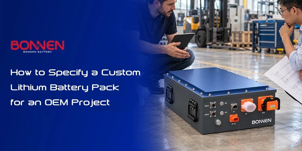
OEM Battery System Design Checklist
Before contacting a battery manufacturer, prepare as much of the following information as possible.
| Project Information | What to Provide |
|---|---|
| Boat application | Leisure boat, workboat, tender, yacht, passenger boat, etc. |
| Motor | Manufacturer, model, rated and peak power |
| Electrical system | 48V, 72V, 96V, or other platform; permitted operating voltage range |
| Battery energy | Required kWh or target operating time |
| Power demand | Continuous and peak battery-side current or power |
| Battery installation | Available dimensions, mounting requirements, weight limits |
| Battery arrangement | Single pack, parallel packs, or other approved architecture |
| Charging | Shore power, charger model, solar, generator, charging limits |
| Communication | CAN protocol, interface documents, display requirements |
| Safety | Applicable standards, installation and protection requirements |
| Environment | Temperature, moisture, vibration, corrosion exposure |
| Project scale | Prototype quantity and estimated production demand |
It is fine if you do not have every answer yet.
However, the motor model, voltage range, power demand, operating time, and installation space are excellent starting points.
Working with a Custom Marine Battery Manufacturer
A custom battery manufacturer ⇱ should review more than nominal voltage and ampere-hours.
For an OEM project, battery development may involve cell selection, BMS configuration, electrical interfaces, enclosure design, cooling requirements, current capability, and integration testing.
At Bonnen Battery, we develop custom marine lithium battery solutions ⇱ for electric propulsion applications, including 48V, 72V, 96V-class, and higher-voltage battery systems.
Our engineering team can evaluate battery voltage, capacity, mechanical dimensions, BMS requirements, and communication options according to the needs of each project.
Explore our Custom Marine Lithium Battery Systems or browse the Marine Battery Product Range ⇱.
11. FAQ
1. What is an electric boat battery system architecture?
It is the arrangement of battery packs, electrical protection, power distribution, motor controllers, charging equipment, and communication devices in an electric boat. It defines how the system delivers power, manages charging, exchanges information, and responds to faults. A complete architecture considers both physical electrical connections and the operating logic that allows the equipment to work together.
2. What components are required for an electric boat battery system?
A typical system includes a lithium battery bank, BMS, electrical protection, a motor controller, an electric motor, and suitable charging equipment. Depending on the design, it may also require a PDU, contactors, pre-charge circuit, DC/DC converter, system controller, battery monitoring display, and communication gateway. The exact components depend on motor power, battery voltage, vessel type, and required safety functions.
3. What battery voltages are commonly used in electric boats?
Electric boat systems may use 48V-class, 72V-class, 96V-class, or higher-voltage batteries. The right choice depends on the motor controller, propulsion power, current requirements, and available system components. A common LFP configuration may have a nominal voltage of 51.2V, 76.8V, or 102.4V, respectively. Exact voltage specifications depend on the cell chemistry and battery configuration.
4. What is the difference between a 48V and 72V electric boat battery?
The main difference is operating voltage and the resulting current needed for the same power. A 72V-class system typically operates at a higher voltage, allowing lower current for an equivalent electrical load. This may reduce some distribution challenges, but the motor controller, charger, protective devices, and complete system must support the selected battery voltage.
5. Should I choose a 72V or 96V battery for my electric boat?
Start with the propulsion motor controller’s permitted operating voltage range. A 72V-class system can be a useful choice when the propulsion equipment is designed for it. A 96V-class system may require less current for the same electrical power, but it also has different voltage and safety requirements. Neither is universally better. The correct choice depends on the complete electrical system.
6. Is a 72V lithium battery always exactly 72V?
No. “72V” can describe a battery platform rather than an exact nominal voltage. For example, 24 LFP cells in series provide a nominal voltage of 76.8V. Other lithium chemistries and series configurations may produce different nominal voltages. Always confirm the battery’s minimum, nominal, and maximum operating voltages before selecting a motor controller or charger.
7. Can I connect multiple 72V marine lithium batteries in parallel?
Yes, provided the battery packs and complete electrical system are designed and approved for parallel operation. Compatible packs must have suitable protection, current-sharing arrangements, monitoring, and fault handling. Their nominal voltage should match, and the manufacturer must confirm the allowable configuration. Do not assume every standalone 72V battery can be connected in parallel.
8. Do parallel marine batteries need a master BMS?
Not always. Some battery systems use internal coordination between compatible modules, while others use a master BMS or a separate system controller. The right arrangement depends on battery hardware and the control functions required by the propulsion system. Larger battery banks often benefit from centralized information about available power, operating limits, and faults.
9. Why does an electric boat battery system need a PDU?
A Power Distribution Unit helps organize connections between the battery bank and electrical equipment. Depending on the system, it may contain busbars, contactors, fuses, sensors, and other protective devices. It can simplify electrical distribution and support safe connection and disconnection. Some compact systems integrate similar functions into the battery enclosure.
10. What is a pre-charge circuit in an electric boat?
A pre-charge circuit controls the initial charging of capacitors inside connected electrical equipment, especially motor controllers. Without suitable pre-charge, connecting a battery directly to discharged capacitors can create high inrush current. The system uses a controlled connection to raise the DC-link voltage before completing the main power path. Its design must match the equipment.
11. Does every electric boat need a pre-charge system?
Not necessarily. The requirement depends on the motor controller, DC-link capacitance, internal equipment design, and system architecture. Some propulsion equipment includes an approved internal pre-charge function. Others require external components. The equipment manufacturer’s integration instructions should determine the correct arrangement.
12. What is the role of the BMS in electric boat propulsion?
The BMS monitors battery conditions and manages battery-related protection functions. Depending on its design, it may report voltage, current, SOC, temperature, operating limits, and faults to other equipment. It may also control contactors and coordinate charging. However, the BMS does not replace every electrical protection device or the complete propulsion system controller.
13. Can a marine battery BMS communicate directly with a motor controller?
Yes, if both devices support compatible communication and operating logic. They may use CAN bus or another defined interface. Engineers need to verify the physical connection, communication settings, message definitions, control requirements, and fault response. Two devices with CAN connectors are not automatically compatible.
14. Can a marine lithium battery communicate with NMEA 2000?
Yes, if its monitoring equipment supports the appropriate NMEA 2000 interface or uses a compatible gateway. A standard battery CAN port does not automatically provide NMEA 2000 communication. The equipment must transmit suitable marine network messages, and compatibility should be checked for the actual devices and installation.
15. Can I display battery SOC on a Simrad multifunction display?
Potentially, yes. The battery data must reach the Simrad system through a supported NMEA 2000 interface or another compatible integration method. Available information depends on the battery monitoring device, supported messages, and display model. A suitable gateway may be required when the battery BMS uses a proprietary CAN protocol.
16. Can a 72V or 96V marine battery communicate with Victron equipment?
Communication may be possible in certain system architectures, but it is not guaranteed. Engineers must confirm the specific Victron equipment, supported battery protocol, operating voltage limits, and control requirements. A Victron GX device receiving battery information does not automatically confirm that the complete 72V or 96V propulsion and charging system is supported.
17. How do I calculate battery capacity for an electric boat?
Start with expected battery-side electrical power consumption and required operating time. Multiply average power in kW by operating hours to estimate energy demand in kWh. Then consider usable SOC range, temperature, aging, auxiliary loads, and reserve margins. Actual propulsion power should be based on vessel performance data or realistic operating estimates rather than motor nameplate power alone.
18. How long will a 30 kWh battery power an electric boat?
It depends on actual energy consumption and usable battery capacity. For example, if a 30 kWh battery bank provides 24 kWh of usable energy and the boat draws an average of 10 kW, the simplified operating time is 2.4 hours. Real performance depends on boat speed, hull resistance, water conditions, auxiliary loads, and battery operating limits.
19. What happens if one battery fails in a parallel system?
The result depends on the protection and control architecture. A properly designed system may isolate the affected battery and reduce available propulsion power. However, the remaining batteries must not be overloaded. Engineers should define how current limits are updated, how faults are reported, and whether controlled continued operation is permitted after one pack becomes unavailable.
20. What information should I send to a marine battery manufacturer?
Start with the boat application, motor manufacturer and model, operating voltage range, continuous and peak power, target running time, and available battery installation space. Also provide charging requirements, communication protocol, environmental conditions, and planned production volume. If available, include electrical drawings, controller specifications, and communication documents. These details help the manufacturer evaluate the complete system rather than quoting only battery capacity.
Conclusion
A successful electric boat battery system starts with the right architecture, not just the right battery capacity.
Whether the boat uses a 48V, 72V, 96V, or higher-voltage battery platform, the battery, BMS, PDU, motor controller, charger, and communication network must work together under both normal and fault conditions.
Voltage selection, parallel battery control, pre-charge, electrical protection, and equipment compatibility all affect the final result.
For OEM boat builders, planning these connections before ordering batteries can save considerable development time and avoid expensive changes during integration.
Developing an electric boat or marine propulsion project?
Bonnen Battery provides custom lithium battery solutions ⇱ for electric boats, including configurable 48V, 72V, 96V-class, and higher-voltage battery platforms.
Share your motor specifications, target capacity, battery installation space, and communication requirements with our team. We can help evaluate a suitable battery configuration for your project.
Contact Bonnen Battery↓ now and let us help you power your adventures with the best Electric Boat Battery System technologies.
© [Bonnen Battery] and [www.bonnenbatteries.com]. Unauthorized use and/or duplication of this material without express and written permission from this site’s author and/or owner is strictly prohibited. Excerpts and links may be used, provided that full and clear credit is given to [Bonnen Battery] and [www.bonnenbatteries.com] with appropriate and specific direction to the original content.