Last Updated on 03/02/2025 by Bonnen Battery

What Is Cell to Pack (CTP) Battery Technology? Key Design Considerations for Success
● What is a CTP battery?
A CTP battery stands for Cell-to-Pack ⇱. It’s a way of putting together battery packs that makes them lighter and more efficient. Instead of using extra parts, like modules, to hold the cells together, CTP directly connects the cells into the pack. This means there are fewer pieces and less weight.
When we discuss grouping efficiency ⇱, we mean the ratio of the weight of the bare cells to the weight of the whole battery pack. For a CTP battery, the efficiency is about 80%.
This means the cells weigh more in the pack. As a result, there is less space for extra parts. This makes the battery lighter and more powerful!
● How are the two main trends of CTP driven?
At present, CTP is mainly promoted from two aspects:
1. Try to design large modules to reduce the weight of the structural parts brought by multiple small modules. In some small electric vehicles, the battery cells are now made into one large module. This is different from the past, when there were two to three smaller modules.
2. Install the battery cells directly into the battery pack. The lower shell parts of the battery pack are also part of the battery module. One problem that needs to be solved with this idea may be how to weld the busbar. The general welding equipment platform cannot accommodate such a large-sized “module”.
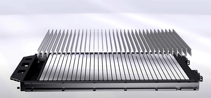
● How is the CTP module constructed? What key factors should be considered?
Basic construction of the module
1. The number of cells in series and parallel
The modules in a single battery pack are generally connected in series
2. The spacing of the cells
Reasonable gaps can help the battery cells release heat. They also allow for the installation of cooling or heating devices. This improves how space is used.
3. Battery cell partition material and form
The main rule for choosing materials for cell partitions is to reduce heat transfer between cells. These materials should also provide some insulation. For prismatic cells, the materials need to be elastic enough to handle cell expansion.
4. Fixed installation point location of the module
The installation point’s location should be based on the battery pack’s layout. We also need to consider how reliable the module is under vibration.
5. Choose and design the liquid cooling parts and heating parts.
Also, plan where to place the docking ports for the liquid cooling system, including the inlet and outlet.
This thermal system component generally establishes several sets of standard solutions or standard docking connectors to save costs.
6. Design of busbar and welding to battery cell tabs
Busbar design is now shifting to lightweight aluminum. This change considers how much current they carry and the heat they generate. Designers are also working to improve the shape of busbars.
7. Voltage and temperature collection wiring harness layout
Voltage collection harness and temperature collection harness are generally called Vsense and Tsense wires. The low-cost solution is to directly use wires with nickel sheets to weld to the bus.
Mid-to-high-end products generally use FPC (flexible circuit board ⇱) to integrate temperature sensing/fuse/voltage collection functions. The cost is generally 2-3 times that of the harness, or even higher. The advantage is easy installation and space saving.
8. Determination of structural parts shape and materials
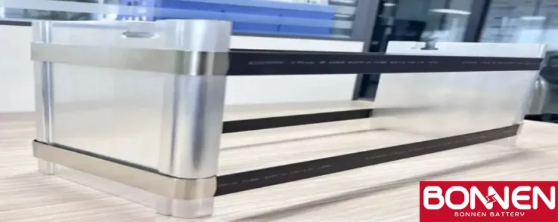
Structural parts are relatively flexible and open. Commonly used structural parts materials include ABS+PC, sheet metal (cold-rolled steel plate), aluminum profiles, etc. The design of structural parts affects the strength and reliability of the module. It also shows the skill of pack design.
9. Auxiliary materials
Generally refers to materials that serve as insulation partitions or high-voltage protection, such as insulating paper, high-voltage terminal protective covers, etc.
The above are basically some important components of module design. Each part is constantly evolving and iterating. There is no so-called unchanging standard module design, and the design ideas are becoming more and more mature.
● CTP process requirements
1. Module stacking
The battery cells and end plate assemblies are stacked into modules. When stacking, care must be taken not to overflow glue.
When stacking, the battery cells need to be aligned on both sides of the module. Alignment mechanisms are required on both sides, and the side plane tolerance is ≤0.5mm. The contact between the stacking tooling and the battery cells must not cause damage to the battery cells.
You can choose the reference surface for stacking the battery cells based on Party B’s technical level. It also depends on the size tolerance range of the battery cells.
The current height tolerance for the battery cells is 0.5mm. The busbar is hard, but the horizontal tolerance of the pole surface must be 0.3mm or less. There should be no welding defects due to height differences in the Z-direction.
During the module stacking process, the components and cells have positioning mechanisms. They are stacked in the center. Each stacked component needs to be shaped and compacted (length and width) to prevent the cells from short-circuiting during the entire process.
The battery and its parts should not be damaged. The blue insulation film on the battery must also remain intact.
Before and after stacking, it should be possible to determine whether the polarity of the cells complies with the series and parallel rules of the module. When an abnormality is determined, an alarm should be issued.
2. Module bundling
The upper strapping material on the battery cell is made of steel. It comes prefabricated in a rectangular shape.
The steel strapping is put into the pressurized module by hand. The lower strapping material is PET. It is bundled, fastened, and tied by a baler. The fastening force and clamping force are adjustable from 150-600kgf. The interface of the PET strapping is manually wrapped with cloth-based tape for protection to prevent temperature or burrs from damaging the battery cell.
The module length direction measures the module length when it is under pressure. This happens during the pressurization process. It also allows for real-time measurement of the module length. Additionally, it records the module clamping force, which is usually less than 10,000 kgf.
The pressure and module length can provide real-time anti-fool logic. They can also alert and stop if any parameter goes over the limit. The module’s clamping force and size can be tracked. The assembly pressure accuracy of the equipment is 1%, and the length measurement accuracy of the equipment is 0.2mm.
The center distance of the module end plate installation holes needs to be finally controlled. After the strapping, the center distance of the module end plate needs to be measured to see if it is within the required range. Clamping tooling is required to ensure the positioning of all module components during the strapping process. The tolerance of the module length and width direction is ≤±0.2mm.
During the process of stacking and bundling, the battery module is shaped by special tools. These tools help keep the module’s length direction steady. Safety design should be considered during module grabbing. The mechanical gripper is an integral grip, and it is prohibited to grab and flip only through the end plate lifting hole.
Insulation protection measures must be planned when inserting the steel belt into the module. This should be done from the direction of the battery cell pole. Since the steel belt arrives in a rectangular shape. If the module structure is inverted stacking, embed the steel belt in the pallet first. This needs to be noted in the next steps.
● Expansion force
At present, most battery cell modules adopt the CTP process, which cancels the traditional side panel design. Since the side panel is cancelled, there is no link between the side panel and the end panel. This means they cannot resist the expansion force of each battery.
To resist the expansion force of each battery, the module-free structure uses strapping and end panels. These parts clamp the battery pack and help control the expansion force.

At present, a preload is applied during the assembly of general modules. There is no particular systematic theoretical explanation for the appropriate preload. At present, 100-200AH batteries generally apply about 3-4KN, but due to assembly reasons, the error is relatively large.
After the battery has been used many times, we need to know how much it will expand. We also need to see if the parts will get damaged. This is a big concern. Some current data show that the expansion force of the battery ranges from a few KN to 20+KN. At the same time, the expansion of the battery may also cause the welded busbar solder joints to fall off. This problem already exists in many modules, and this also poses a new challenge to the busbar design.
● Module expansion displacement simulation and testing
If the reserved expansion space is too small, the battery module’s outer contour may exceed the standard. This can lead to failure in meeting customer requirements. If the reserved expansion space is too big, the battery module may be designed with low volume density. This design may not have any competitive advantage.
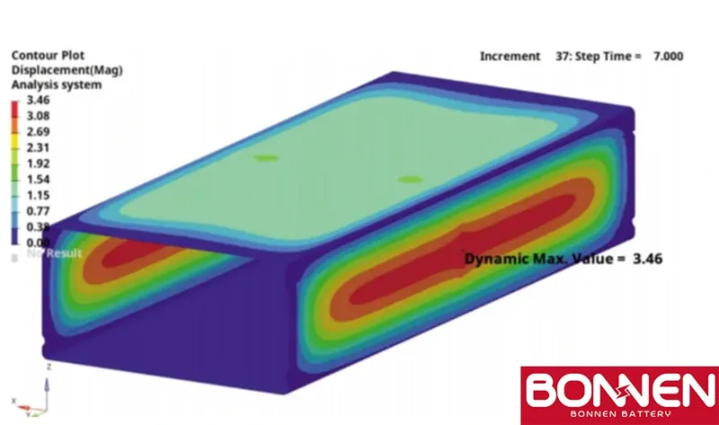
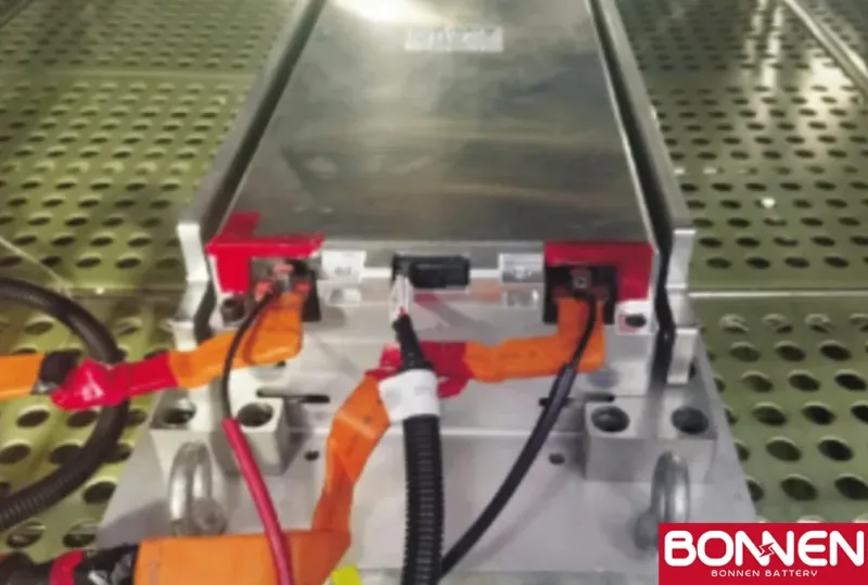
In order to test the expansion displacement of the module, a comprehensive test platform was built. The platform mainly includes constant temperature test box, charge and discharge tester, displacement detection tooling, experimental module and other components. The experimental module is selected to be consistent with the simulation analysis module, and the module is placed in a special expansion displacement detection tooling. The positioning of the module is consistent with the positioning method in the system.
In the development process of high-energy-density batteries, silicon-based negative electrode materials ⇱ have become a hot research topic because their theoretical specific capacity far exceeds that of traditional graphite negative electrodes. However, the volume expansion problem of silicon-based negative electrodes during charging and discharging is relatively serious, which poses a huge threat to the cycle performance and safety of the battery.
In the future, researchers need to further explore the expansion mechanism of silicon-based negative electrodes and develop silicon-based negative electrode materials with low expansion characteristics by optimizing material structure and improving preparation processes.
For example, silicon nanoparticles or silicon-based composite materials are prepared using nanotechnology, and their special structure is used to alleviate volume expansion; or the stability between silicon-based materials and electrolytes is enhanced through surface modification and other methods, reducing the rupture and repair reaction of SEI membranes caused by expansion, thereby reducing the generation of expansion force.
The rapid development of fast charging technology ⇱ has also put forward higher requirements for the control of the expansion force of lithium batteries. Fast charging will cause the chemical reaction rate inside the battery to accelerate sharply, resulting in the temperature of the electrode material and uneven distribution of lithium ion concentration, which in turn aggravates the expansion of the battery.
To meet this challenge, we need to develop electrolytes with high ionic conductivity and thermal stability. This will help lithium ions move quickly in and out of the electrode material. This is important for fast charging and discharging. It will also reduce local volume changes. Additionally, we must optimize the battery’s thermal management system ⇱.
Through efficient heat dissipation structure design and intelligent temperature control strategy, the heat generated by the battery can be dissipated in time to avoid the problem of aggravated expansion caused by excessive temperature. For example, liquid cooling ⇱ or phase change cooling technology, combined with high-precision temperature sensors and intelligent controllers, can achieve precise control of battery temperature, ensure that the temperature of the battery is always within a safe range during fast charging, and thus effectively control the growth of expansion force.
In addition, the continuous emergence of new materials and new processes also provides broad prospects for solving the problem of lithium battery expansion force.
Graphene-based materials are expected to play an important role in lithium batteries due to their excellent mechanical properties, high conductivity and good chemical stability. For example, applying graphene as an additive or coating material to electrodes can enhance the structural stability of the electrodes, inhibit the volume expansion of electrode materials, and at the same time improve the conductivity of the battery and enhance the overall performance of the battery.
Moreover, new battery manufacturing processes, such as solid-state battery technology ⇱, use solid electrolytes to replace traditional liquid electrolytes, which can not only significantly improve the energy density and safety of batteries, but may also fundamentally change the expansion mechanism inside the battery. Solid electrolytes have high mechanical strength and stability, can better limit the volume changes of electrode materials, reduce the generation of expansion forces, and open up new directions for the development of lithium batteries.
Contact Bonnen Battery↓ now and let us help you power your adventures with the best in EV lithium battery technology.
© [Bonnen Battery] and [www.bonnenbatteries.com]. Unauthorized use and/or duplication of this material without express and written permission from this site’s author and/or owner is strictly prohibited. Excerpts and links may be used, provided that full and clear credit is given to [Bonnen Battery] and [www.bonnenbatteries.com] with appropriate and specific direction to the original content.