

Custom Battery System Engineering
96V Lithium Battery Systems for EVs, Marine & Industrial Equipment
Custom 96V battery packs engineered around your motor power, installation space, runtime, peak current, charging method and communication requirements.
Final architecture is confirmed against the motor, controller, charger and operating requirements.
96V Battery at a Glance
96V / 100V / 102V Platforms
Related architectures are evaluated separately for nominal and maximum charge voltage.
LiFePO4 & NMC Options
Chemistry selection depends on energy, power, packaging, thermal and lifecycle priorities.
Custom BMS & CAN Integration
Communication and control interfaces can be configured around the host system.
Custom Enclosure & Interfaces
Dimensions, mounting, connectors and service access are reviewed as one package.
Prototype to Volume Production
Development support can progress from requirements review through pilot and production.
Existing Platforms
Explore Our 96V Battery Systems
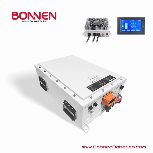
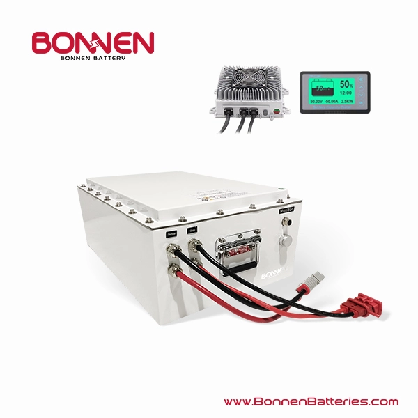
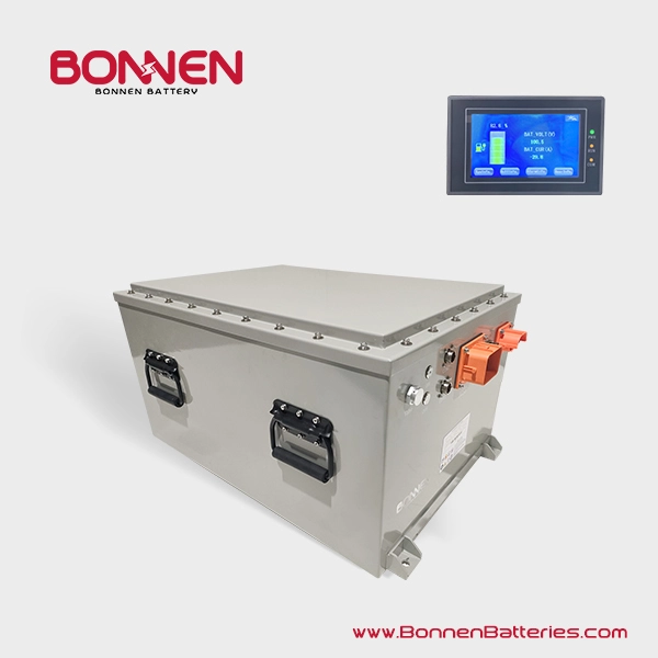
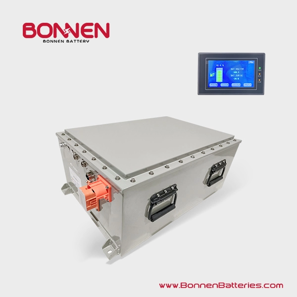
Browse existing Bonnen battery platforms for electric vehicles, marine propulsion, AMRs and industrial applications. Specifications can be adapted after an engineering review of your project requirements.
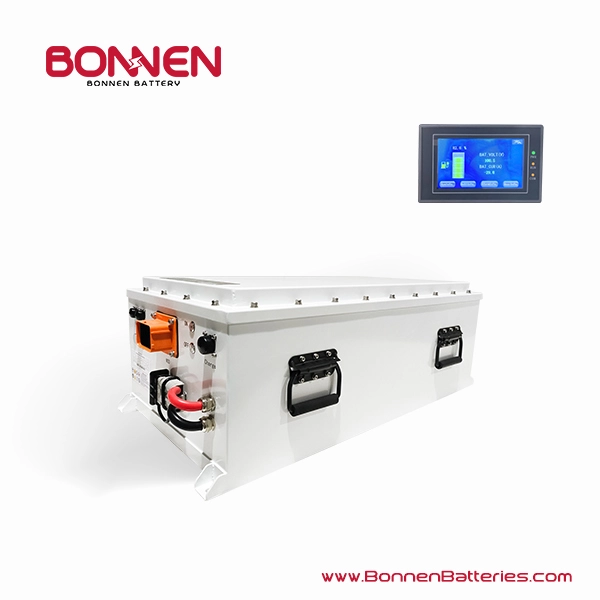
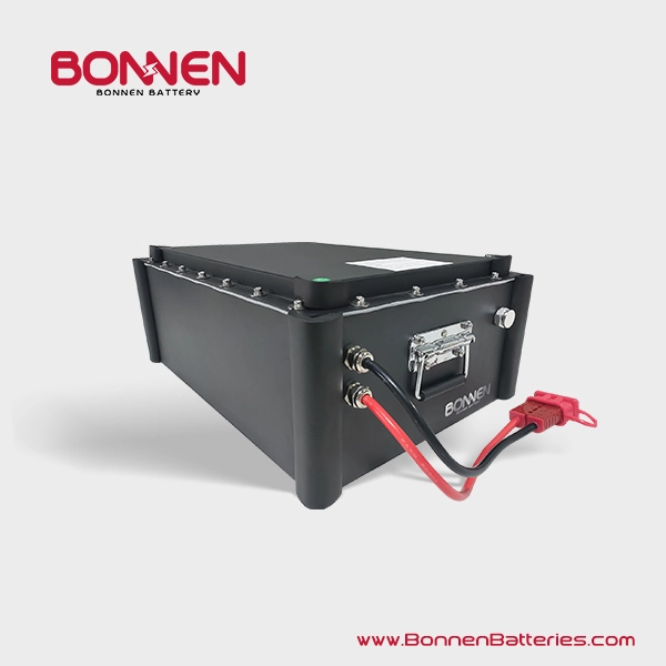
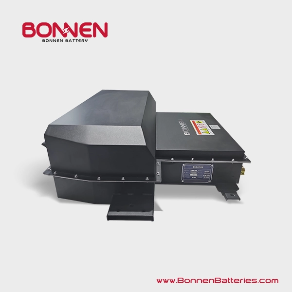


Application Fit
Where 96V Battery Systems Fit
A 96V platform can support varied duty cycles, but each installation still needs its own electrical, mechanical, charging and environmental review.

Electric Vehicles & EV Conversions
Match motor and controller voltage, peak acceleration current, available chassis volume and the charging architecture.

Electric Boats & Marine Propulsion
Review propulsion load, machinery-space layout, charging access, communication and the operating environment together.

AMRs, AGVs & Material Handling
Balance runtime, charge windows, peak traction demand, fleet communication and serviceable installation geometry.

Utility & Specialty Vehicles
Low-speed and task-specific vehicles often require packaging, mounting and interface decisions that standard catalogue dimensions cannot resolve.

Industrial & Outdoor Equipment
Duty cycle, vibration, low-temperature operation, thermal strategy and connector protection must be evaluated for the actual machine.
Engineering Context
Why Choose a 96V Battery System?
For the same power demand, raising system voltage generally reduces the current required. Current affects conductor sizing, controller loading, resistive losses and thermal management.
That can make 96V a useful bridge between lower-voltage equipment and higher-voltage traction architectures—but it is not an automatic fit for every project.
This relationship explains the trade-off. It does not replace a duty-cycle, peak-current and component-compatibility review.
- Confirm nominal voltage and maximum charge voltage.
- Check motor controller and charger operating ranges.
- Define continuous, transient and regenerative current.
- Coordinate isolation, switching and service strategy.
A relative voltage architecture view
Higher system voltage can reduce current for a given power level, while adding different component and safety requirements.
The positions show a relative progression only. They are not fixed power boundaries or a substitute for component-level engineering.
System Definition
How We Configure a 96V Battery System
The final architecture can be configured around project requirements. Not every option applies to every product or application.
Capacity & Runtime
Translate Ah, kWh, range or operating hours into a realistic duty-cycle target.
Continuous & Peak Current
Define steady load, acceleration or startup peaks, regenerative events and protection margins.
Cell Chemistry
Evaluate energy density, power, thermal behavior, lifecycle priorities and packaging constraints.
Enclosure & Mounting
Coordinate maximum dimensions, orientation, structure, service access and machine interfaces.
BMS & Communication
Align CAN, RS485 or I/O behavior with the controller, display, charger and host equipment.
Protection & Switching
Configure fusing, contactors, pre-charge and service disconnect strategy as required.
Charging Interface
Match charger voltage, available input power, connection method and operating window.
Thermal Management
Assess heat generation, ambient conditions, charging profile and available airflow or cooling.
Operating Environment
Review temperature, vibration, moisture exposure, contamination and maintenance access.
Illustrative system relationship
Component selection and boundaries are confirmed after the electrical, mechanical and operating requirements are known.
- Cells
- Mechanical Structure
- BMS
- Protection & Switching
- Communication
- Charger / Motor Controller
Custom Engineering Path
Don’t See the Exact 96V Battery You Need?
Most OEM projects require more than selecting a battery by voltage and capacity. Motor power, peak current, available installation space, runtime, charging method, operating environment and communication interface all affect the final battery design.
An existing platform can be a starting point. The final system still needs to be reviewed against the machine, controller, charger, packaging and duty cycle.

Project Brief
The Inputs That Shape Your Battery
These inputs connect the battery specification to the real load, installation and operating environment.
| What We Need | Useful Project Information |
|---|---|
| Application | EV, boat, AMR, utility vehicle or industrial equipment |
| Motor or Load | Voltage plus rated and peak power, including startup or acceleration demand |
| Battery Target | Ah, kWh, vehicle range, operating hours or duty-cycle profile |
| Installation Space | Maximum length × width × height, mounting orientation and service access |
| Current Demand | Continuous current, peak current, event duration and regenerative current |
| Charging | Charger details, charging window and available input power |
| Communication | CAN, RS485 or I/O requirements and host-controller information |
| Environment | Temperature, vibration, moisture, contamination and expected service conditions |
| Volume & Timing | Prototype quantity, estimated production demand and target programme milestones |
Development Workflow
From Requirements to Production Readiness
Each gate reduces uncertainty before the project advances. The exact scope depends on the application and agreed validation responsibilities.
Requirements Review
Align voltage, load, runtime, space, charging, communication, environment and programme targets.
System Architecture
Define the proposed electrical, mechanical, control, protection and interface approach.
Prototype
Build the agreed configuration for fit, interface and functional evaluation.
Integration Validation
Evaluate the battery with the charger, controller, machine and representative duty cycle.
Pilot Build
Refine manufacturability, assembly controls, documentation and integration details.
Production
Move forward after requirements, responsibilities and release criteria are agreed.

Integration Discipline
Review the Battery as Part of the Complete System
A battery cannot be qualified in isolation from the equipment it powers. Interface and validation planning should connect the battery to the host system and the real operating profile.
- Mechanical fit and service accessConfirm envelope, mounting, connector clearance, handling and maintenance paths.
- Electrical compatibilityCoordinate nominal and maximum voltage, current demand, protection, switching and charging.
- Control and communicationCheck messages, states, fault handling and interactions with the charger and controller.
- Application-specific validationAgree representative duty cycles, environments and acceptance responsibilities before release.
FAQs About 96V Lithium Battery Systems
Practical answers for EV builders, marine propulsion projects, industrial equipment manufacturers and system integrators selecting or developing a 96V lithium battery system.
Start With Your Requirements
Get an Engineering Review for Your 96V Project
Share the application, motor or load, target runtime, available space, current demand, charging method, communication and operating environment.